
Device and method for controlling the temperature of a rotating body

Inactive Publication Date: 2007-08-23
MANROLANAD AG
View PDF6 Cites 2 Cited by
  • Summary
  • Abstract
  • Description
  • Claims
  • Application Information

AI Technical Summary

Benefits of technology

[0008] Since the development of a hot spot on the surface of a cylinder causes unbalanced heating of the cylinder, bending of the cylinder occurs, especially when the cylinder is long relative to its diameter. Unbalanced heat input does not occur if the temperature difference due to the hot spot is reduced or completely compensated. The bore that is provided makes it possible, in a way that is practicable and favorable from the standpoint of production engineering, to provide the cylinder with a mechanism for controlling its temperature. The use of a single bore for introducing and removing a fluid for controlling the temperature of the cylinder is a solution which is favorable from the standpoint of production engineering and allows the cylinder to be heated to a temperature that is not susceptible to curvature due to the development of hot spots on the surface of the cylinder.
[0018] It is advantageous for the device of the invention to be based on a conventional cylinder design. In other words, since a bore can be made in a conventional cylinder, a multipart cylinder is not necessary, but rather a conventional cylinder can also be reshaped in connection with a retrofitting.

Problems solved by technology

Since the development of a hot spot on the surface of a cylinder causes unbalanced heating of the cylinder, bending of the cylinder occurs, especially when the cylinder is long relative to its diameter.

Method used


Image

  • Device and method for controlling the temperature of a rotating body
  • Device and method for controlling the temperature of a rotating body
  • Device and method for controlling the temperature of a rotating body

Examples


Embodiment Construction

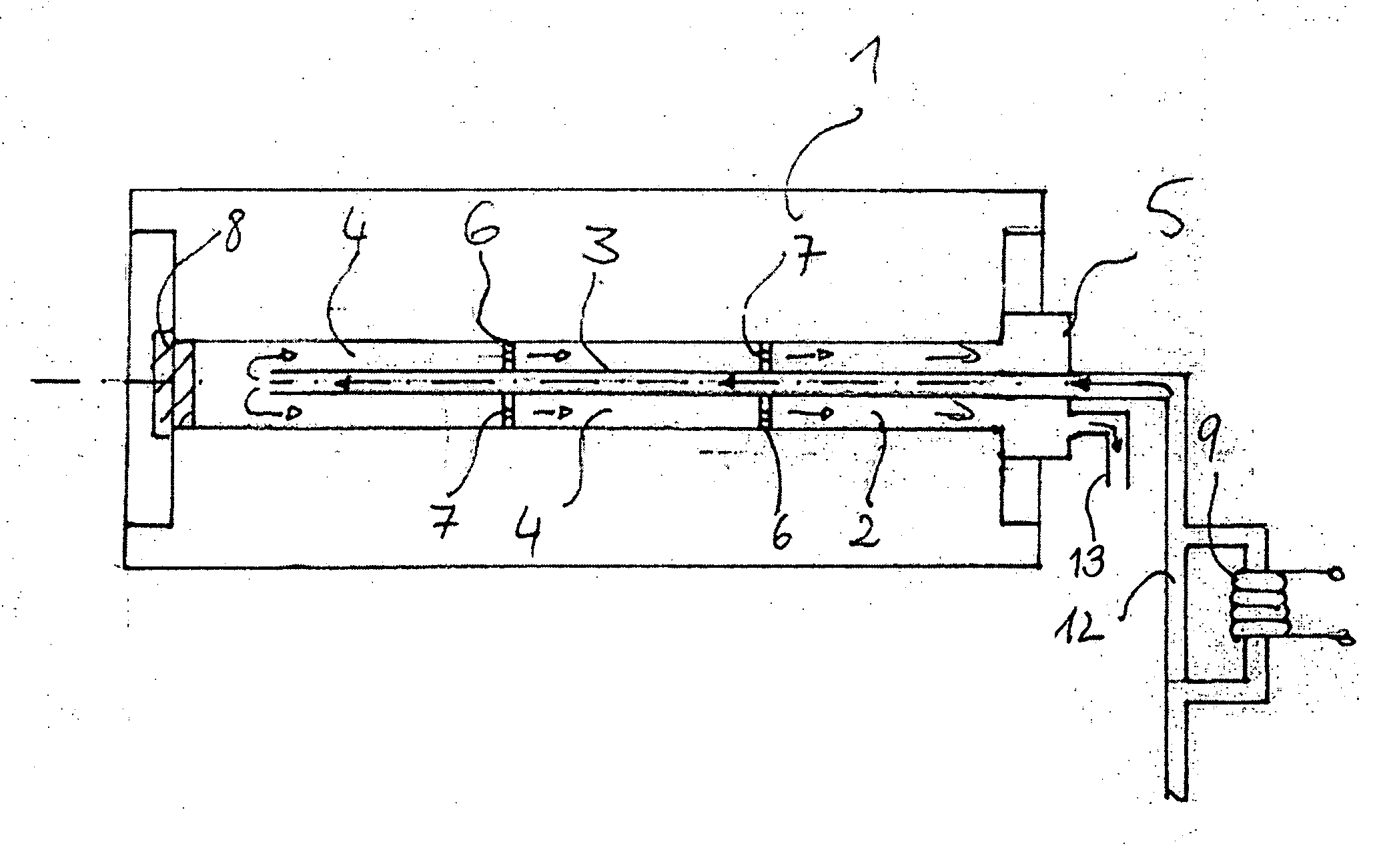
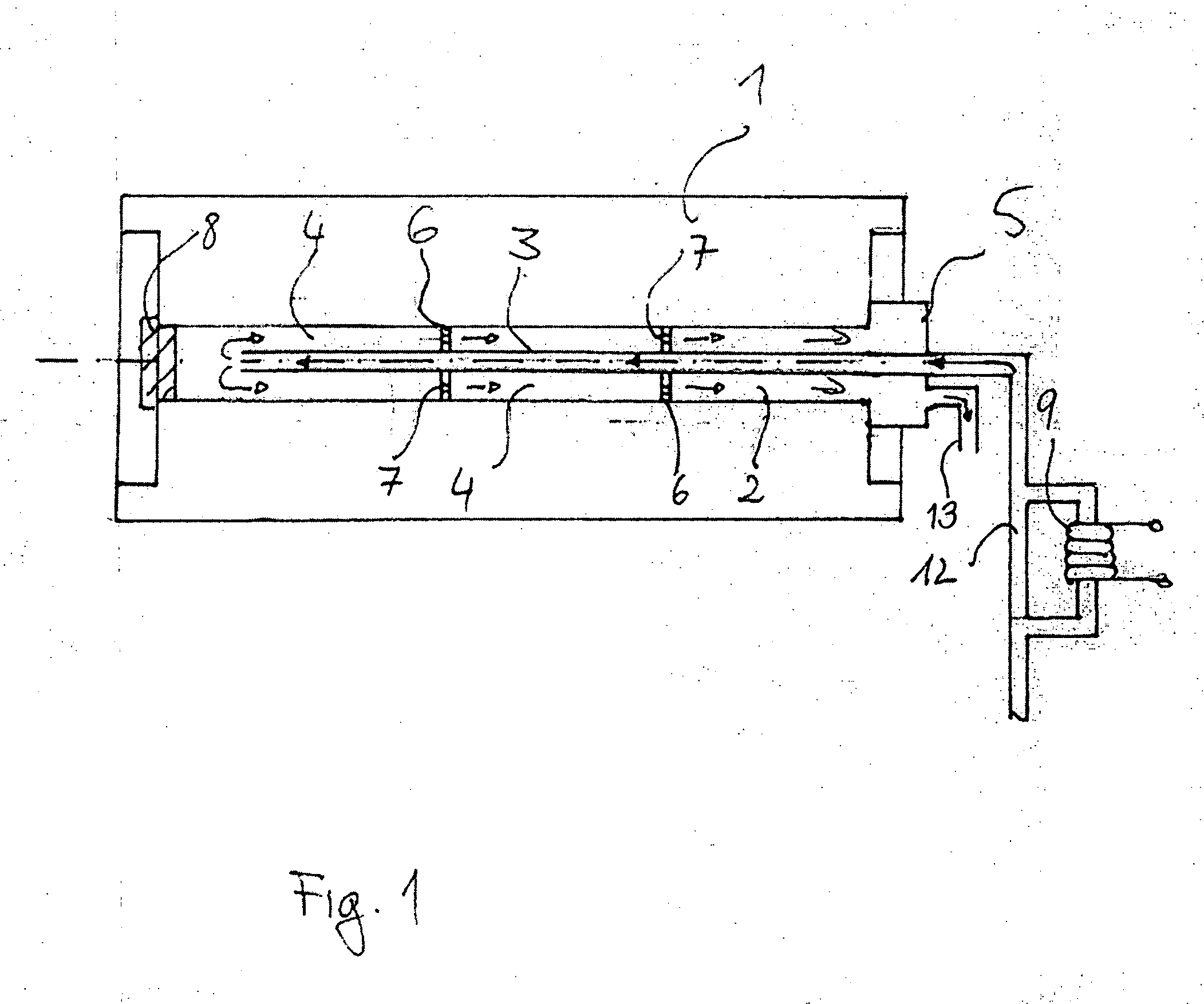
[0023]FIG. 1 shows a cross-sectional view of a blanket cylinder 1 with a bore 2 that passes through it. A supply line 3 is supported in the bore 2 on spacers 6. The spacers 6 have flow regions 7, which in the present case are formed as circular drill holes along the circumference of the spacer 6. The spacers 6 form a return duct 4 having an annular cross-section between the inside wall of the bore 2 and the supply line 3. The supply line 3 and return duct 4 are rotatably joined with the connector 5, which is rigidly mounted on a base of the blanket cylinder.

[0024] The connector 5 is preferably a rotationing union of the type sold by the Deublin Company of Waukegan, Ill. For the embodiment of FIG. 1, a Deublin 57 Series duo-flow union is especially suitable. Such a union can be fixed to a support framework of the rotating cylinder, and has sealed joints connecting the inlet line 12 and discharge line 13 to the supply line 3 and return duct 4 respectively.

[0025] Since the bore 2 pas...


PUM


Abstract

A cylinder of a printing press is provided with an axial bore in which a fluid supply line is supported by spacers forming a return duct having an annular cross section, so that the inlet and the outlet of the fluid are at the same end of the cylinder.

Description

BACKGROUND OF THE INVENTION [0001] 1. Field of the Invention [0002] The present invention concerns a device and a method for controlling the temperature of a rotating body, i.e., especially for controlling the temperature of a cylinder, e.g., a blanket cylinder of a printing press. [0003] 2. Description of the Related Art [0004] In printing presses, the rolling of two cylinders on each other can cause local heating. For example, this can be the case with a blanket cylinder that is fitted with a rubber blanket or rubber sleeve and is rolling on a plate cylinder. The local heat input occurs especially in the area of contact of the blanket cylinder with the channel of the plate cylinder. The phenomenon of local heat input is referred to as the hot spot problem, which can also arise with blank cylinder / blanket cylinder printing units in the area of contact between the blanket cylinders. [0005] The local heat input results in unbalanced linear expansion of the cylinder and thus to curvat...

Claims


Application Information

Patent Timeline
IPC IPC(8): B41F23/04
CPCB41F13/22
Inventor HOFFMANN, EDUARDKANDLBINDER, THOMASMITTELHAMMER, HARALD
Owner MANROLANAD AG
Learn More