
Dynamic vibrational control

a vibration control and dynamic technology, applied in the field of cutting tool methods and systems, can solve the problems of reducing the damping, and reducing the initial total vibration of the drilling tool assembly

Inactive Publication Date: 2007-08-16
SMITH INT INC
View PDF34 Cites 45 Cited by
  • Summary
  • Abstract
  • Description
  • Claims
  • Application Information

AI Technical Summary

Problems solved by technology

Drilling tool assembly vibrations may also result from vibration of the drill bit during drilling.
In general, drilling tool assemblies may experience torsional, axial, and lateral vibrations.
Although partial damping of vibration may result due to viscosity of drilling fluid, friction of the drill pipe rubbing against the wall of the well bore, energy absorbed in drilling the formation, and drilling tool assembly impacting with well bore wall, these sources of damping are typically not enough to suppress vibrations completely.
Vibrations of a drilling tool assembly are difficult to predict because different forces may combine to produce the various modes of vibration, and models for simulating the response of an entire drilling tool assembly including a drill bit interacting with formation in a drilling environment have not been available.
Drilling tool assembly vibrations are generally undesirable, not only because they are difficult to predict, but also because the vibrations can significantly affect the instantaneous force applied on the drill bit.
This can result in the drill bit not operating as expected.
For example, vibrations can result in off-centered drilling, slower rates of penetration, excessive wear of the cutting elements, or premature failure of the cutting elements and the drill bit.
Lateral vibration of the drilling tool assembly may be a result of radial force imbalances, mass imbalance, and drill bit / formation interaction, among other things.
Lateral vibration results in poor drilling tool assembly performance, overgage hole drilling, out-of-round, or “lobed” well bores and premature failure of both the cutting elements and drill bit bearings.
Lateral vibration is particularly problematic if hole openers are used.
Further, increasing the diameter of the wellbore may be necessary if, for example, the formation being drilled is unstable such that the wellbore diameter changes after being drilled by the drill bit.
It is difficult to directionally drill a wellbore with a large diameter bit because, for example, larger diameter bits have an increased tendency to “torque-up” (or stick) in the wellbore.

Method used


Image

  • Dynamic vibrational control
  • Dynamic vibrational control
  • Dynamic vibrational control

Examples


Embodiment Construction

[0050] The present invention relates to a simulation method and / or selection tool wherein the detailed interaction of the drill bit with the bottomhole surface during drilling is considered in conjunction with hole openers, or any other cutting tool used during the drilling of earth formation. Specific embodiments of the present invention relate to methods for calculating and simulating the combined axial, torsional, and / or lateral vibrations of at least one hole opener and a drill bit.

[0051]FIG. 4 shows a general configuration of a hole opener 430 that may be used in embodiments of the present invention. The hole opener 430 includes a tool body 432 and a plurality of blades 438 disposed at selected azimuthal locations about a circumference thereof. The hole opener 430 generally comprises connections 434, 436 (e.g., threaded connections) so that the hole opener 430 may be coupled to adjacent drilling tools that comprise, for example, a drillstring and / or bottom hole assembly (BHA) ...


PUM


Abstract

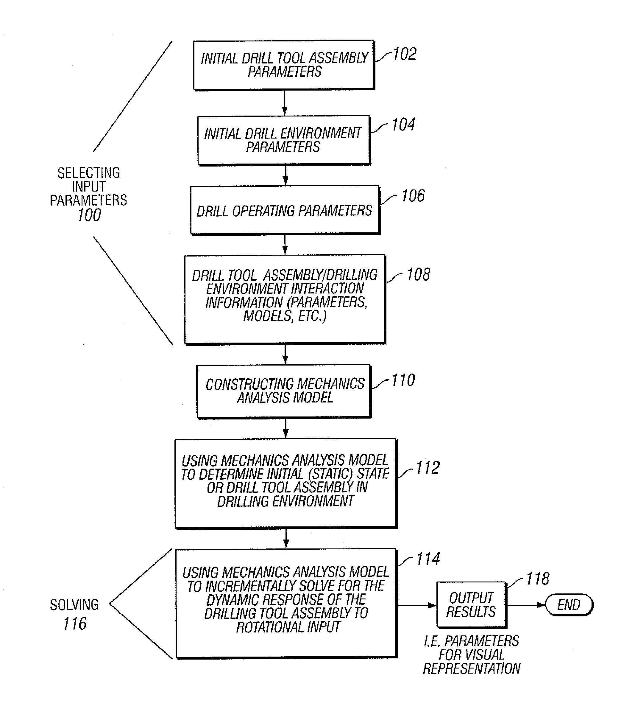
A method for reducing vibration of a drilling tool assembly is disclosed. The method includes modeling the drilling tool assembly based on input parameters, simulating a vibration of a drill string coupled with a vibration of a drill bit, determining an initial total vibration from output parameters generated by the simulation, determining a location for at least one vibrational control device based on the initial total vibration to reduce the initial total vibration, and disposing the at least one vibrational control device on the drill string at the determined location.

Description

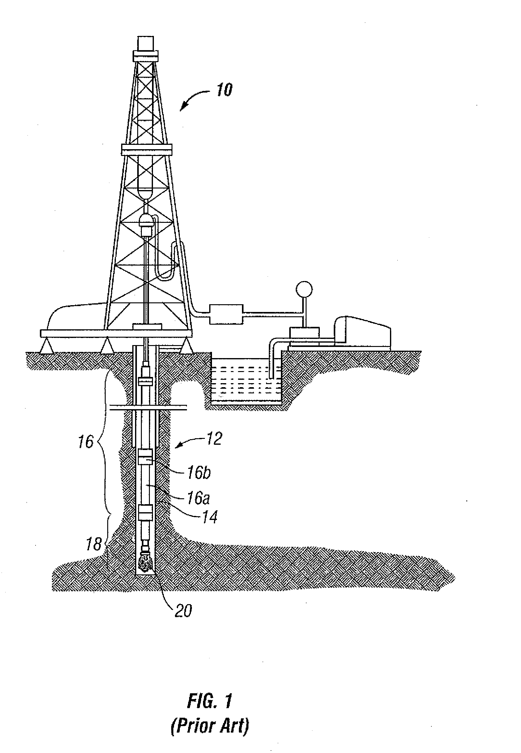
CROSS-REFERENCE TO RELATED APPLICATIONS [0001] This application claims the benefit pursuant to 35 U.S.C. § 120, as a continuation of U.S. patent application Ser. No. 11 / 385,969, filed on Mar. 21, 2006, and continuation-in-part application of U.S. patent application Ser. Nos. 11 / 100,337, filed on Apr. 6, 2005, Ser. No. 09 / 524,088 (now U.S. Pat. No. 6,516,293), 09 / 635,116 (now U.S. Pat. No. 6,873,947), 10 / 749,019, 09 / 689,299 (now U.S. Pat. No. 6,785,641), 10 / 852,574, 10 / 851,677, 10 / 888,358, 10 / 888,446, all of which are expressly incorporated by reference in their entirety.BACKGROUND OF INVENTION [0002] 1. Field of the Invention [0003] The invention relates generally to methods and systems involving cutting tools in oilfield applications. [0004] 2. Background Art [0005]FIG. 1 shows one example of a conventional drilling system for drilling an earth formation. The drilling system includes a drilling rig 10 used to turn a drilling tool assembly 12 that extends downward into a well bore 1...

Claims


Application Information

Patent Timeline
Patent Type & Authority Applications(United States)
IPC IPC(8): G06F17/10
CPCE21B10/00E21B47/12E21B44/00E21B17/10G06F30/20
Inventor HUANG, SUJIAN J.OLIVER, STUARTSTRONACH, GRAHAM
Owner SMITH INT INC
Learn More