Injection mold having shearing flow making part
a technology of injection mold and making part, which is applied in the direction of manufacturing tools, food shaping, drawing profiling tools, etc., can solve the problems of defective products, product defects, and marked decrease in reflected light, and achieve the effect of high quality
- Summary
- Abstract
- Description
- Claims
- Application Information
AI Technical Summary
Benefits of technology
Problems solved by technology
Method used
Image
Examples
first embodiment
[0049]FIG. 7 is a structural view schematically illustrating an injection mold device having a shear flow making part according to the present invention.
[0050] Referring to the drawing, the injection mold device according to the first embodiment includes a mold 41 for manufacturing a plate shaped product (reference symbol B in FIG. 14), a roller 49 installed in an inside of the mold 41, and a driving part for driving the roller 49.
[0051] The mold 41 is constructed with a core plate 45 and a cavity plate 43 which is fitted on an upper portion of the core plate 45, and gates 43a for injecting molten resin into a cavity 47 of the mold are provided at both sides of the cavity plate 43. The gates 43a are located the most appropriate position considering a flow speed, flow length or so on of the molten resin.
[0052] Meanwhile, the roller 49 is a round rod type member which has a predetermined diameter and some portion of an outer peripheral surface of the roller is protruded to the cavit...
second embodiment
[0056]FIG. 8 is a structural view schematically illustrating an injection mold device having a shear flow making part according to the present invention, and there is an advantage that an effect of shear flow can be maximized in comparison with a difficulty of manufacturing parts since a whole surface of a wide moving surface belt 50 instead of the roller in FIG. 7 is slightly protruded and moved.
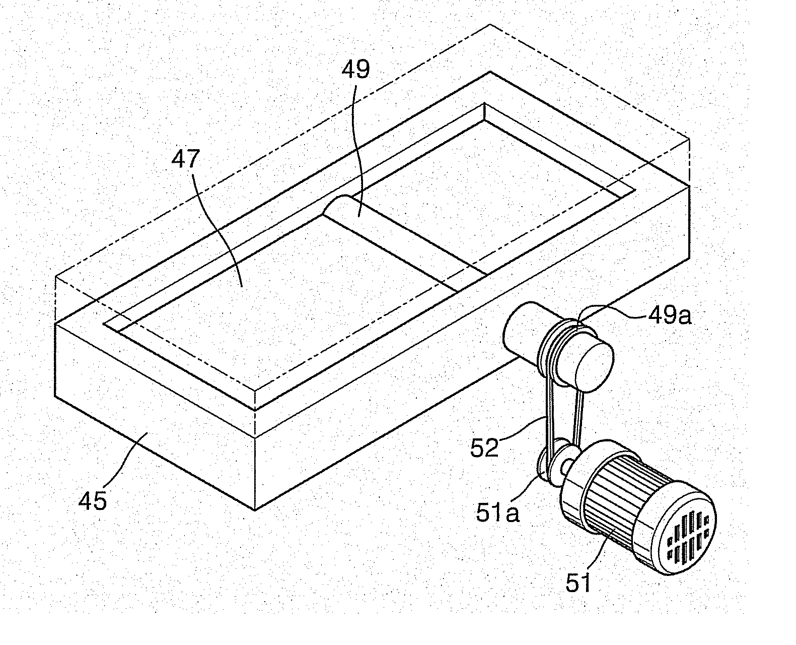
[0057]FIGS. 9 and 10 are partial perspective views illustrating the injection mold device shown in FIGS. 7 and 8, in which a power transmitting connection between the roller 49 and the motor 51 is exemplary illustrated.
[0058] As shown, the roller 49 is rotatively installed at the core plate 45. It is as same as the above description that the some portion of the outer peripheral surface of the roller 49 is protruded t o the upper portion of the core plate 45.
[0059] Particularly, one end portion of the roller 49 extends to a side portion of the core plate 45 and a pulley 49a is secured to t...
third embodiment
[0067] Referring to FIG. 15, the core plate 57 of the injection mold device is provided with multiple rollers 49. The four rollers 49 are rotated at a same rotational speed by the single motor 51. The rotational speed (a rotational direction is also included in the rotational speed) of the roller 49 is adjustable by the controller 53.
[0068] In addition, the power transmitting connection between each roller 49 and the motor 51 may be implemented by any conventional power coupling. Further, an operating time of the roller 49 is same as that in the first embodiment.
[0069]FIGS. 16 and 17 are views for explaining the operation of the injection mold device shown in FIG. 15.
[0070] As shown, the multiple rollers 49 are protruded from the inward facing surface of the core plate 57 to the upper portion. Each roller 49 makes the molten resin, which is filled in the cavity 47 and in contact with the outer peripheral surface of the roller, to flow viscously in the direction of the arrow X so ...
PUM
| Property | Measurement | Unit |
|---|---|---|
| viscosity | aaaaa | aaaaa |
| shearing force | aaaaa | aaaaa |
| structure | aaaaa | aaaaa |
Abstract
Description
Claims
Application Information
 - R&D
- Intellectual Property
- Life Sciences
- Materials
- Tech Scout
- Unparalleled Data Quality
- Higher Quality Content
- 60% Fewer Hallucinations
Browse by: Latest US Patents, China's latest patents, Technical Efficacy Thesaurus, Application Domain, Technology Topic, Popular Technical Reports.
© 2025 PatSnap. All rights reserved.Legal|Privacy policy|Modern Slavery Act Transparency Statement|Sitemap|About US| Contact US: help@patsnap.com


