Injection device
- Summary
- Abstract
- Description
- Claims
- Application Information
AI Technical Summary
Benefits of technology
Problems solved by technology
Method used
Image
Examples
examples
[0108] While the present invention will be described in further detail below with reference to typical examples, it is not intended that the present invention be limited to the examples.
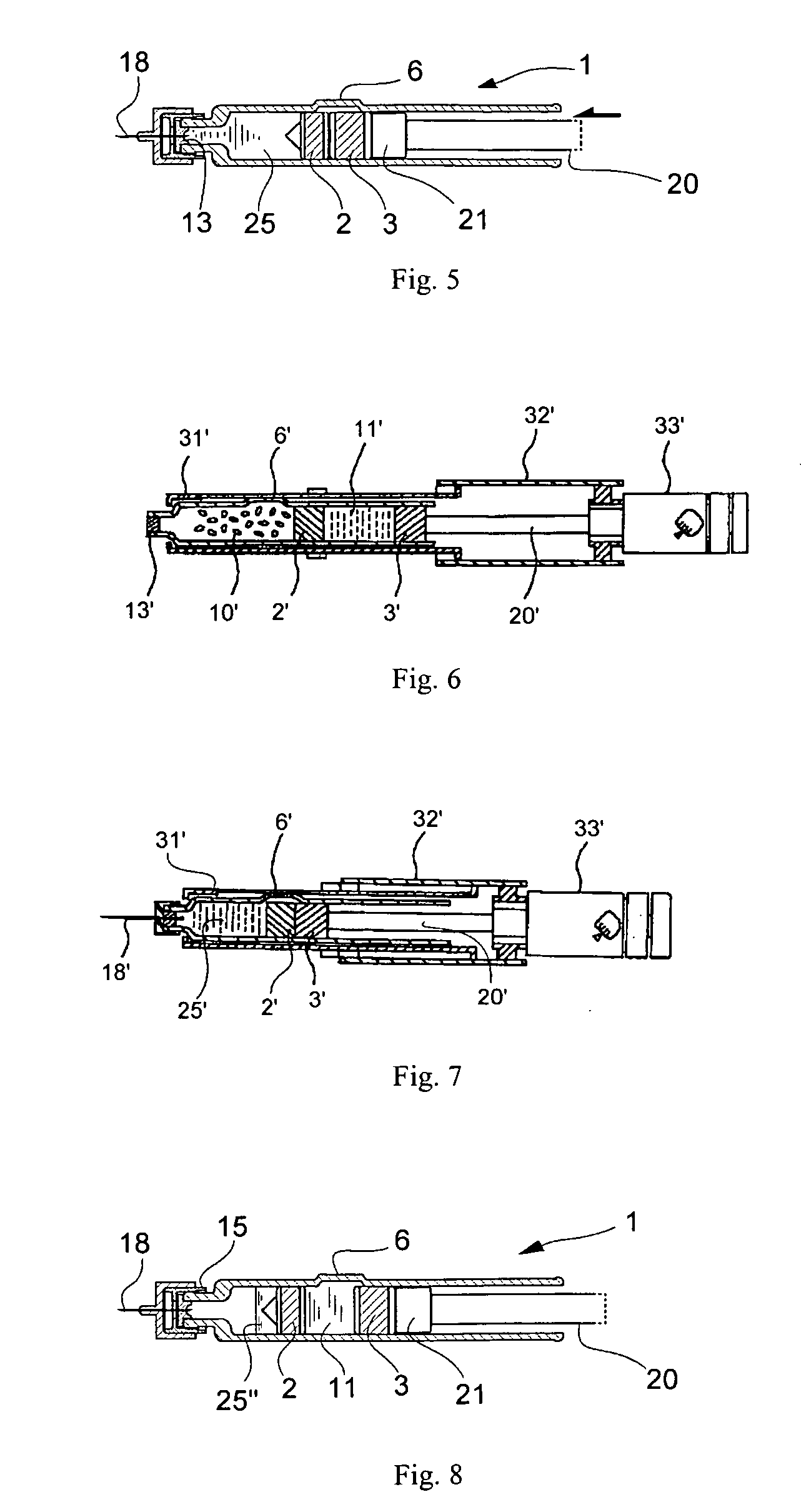
[0109]FIG. 10 illustrates a side cross sectional view of a front casing 31 of the injection device holding a two-compartment syringe 1 with an attached double-ended needle 18. FIG. 11 illustrates a side cross sectional view of a rear casing 32 of the injection device and other associated members such as an ejection volume controller member 33 combined with the rear casing. The numeral 35 indicates a piston rod, and 35h the head of the piston rod 35. Around the piston rod 35 is placed a coil spring 36 between the head 35h of the piston rod 35 and rear part of the rear casing 32. In rear part of the piston rod 35, a pair of racks 42 are formed on both sides of the piston rod. In the area before the racks 42, on both sides of the piston rod 35, a pair of grooves 44, of which one is visible in the figur...
PUM
 Abstract
Description
Claims
Application Information
 - R&D
- Intellectual Property
- Life Sciences
- Materials
- Tech Scout
- Unparalleled Data Quality
- Higher Quality Content
- 60% Fewer Hallucinations
Browse by: Latest US Patents, China's latest patents, Technical Efficacy Thesaurus, Application Domain, Technology Topic, Popular Technical Reports.
© 2025 PatSnap. All rights reserved.Legal|Privacy policy|Modern Slavery Act Transparency Statement|Sitemap|About US| Contact US: help@patsnap.com


