
Radio base station apparatus and transmission power control method

a technology of transmission power and radio base station, which is applied in the direction of power management, sustainable buildings, wireless communication, etc., can solve the problems of increasing the total transmission power of the base station, failure of the apparatus itself, and failure to ensure the signal quality required for signals received by the mobile station terminal from the base station, etc., to achieve stable communication, large communication capacity, and large communication capacity

Inactive Publication Date: 2007-08-09
NEC CORP
View PDF33 Cites 34 Cited by
  • Summary
  • Abstract
  • Description
  • Claims
  • Application Information

AI Technical Summary

Benefits of technology

[0014] It is an object of the present invention to provide a radio base station apparatus and a transmission power control method which restrain an increase in total transmission power and which supply transmission power which ensures ideal reception quality for mobile station terminals of users associated with highly prioritized communication connections, even if the number of used mobile station terminals is increased.
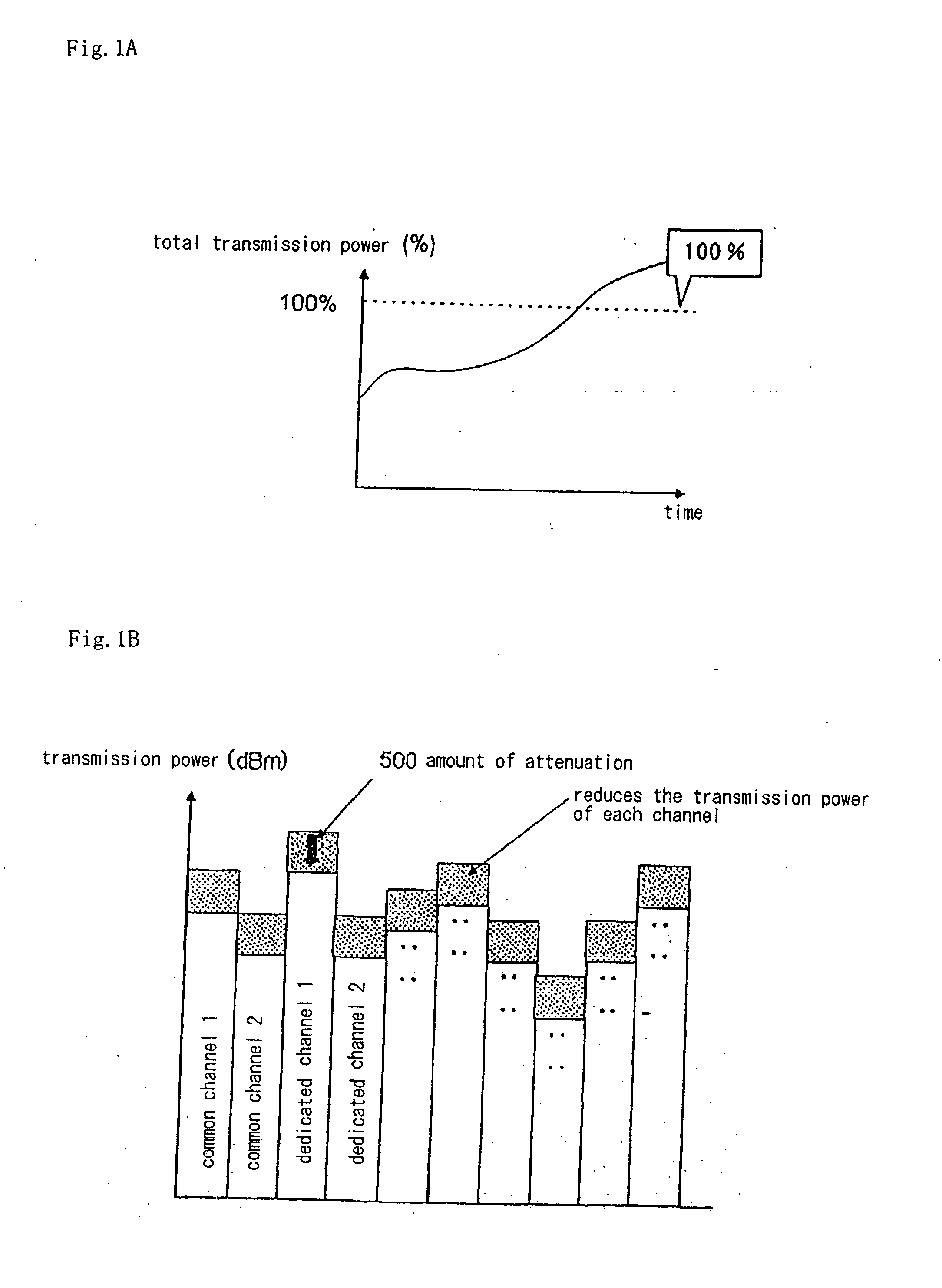
[0015] A radio base station apparatus of the present invention for achieving the above-mentioned object is a radio base station apparatus for communicating with a plurality of mobile station terminals over the air, and comprises a storage unit which has previously stored therein upper limit values of transmission power for the mobile station terminals, a first threshold referenced to determine whether or not the transmission power is reduced, a second threshold larger than the first threshold, and priority levels of the mobile station terminals, and a control unit for monitoring total transmission power which is the sum of the transmission power for all the mobile station terminals connected for mutual communication, by a predetermined value, reducing the upper limit value of the transmission power for the mobile station terminal which is assigned the lowest priority level when the total transmission power exceeds the first threshold, and terminating communication with the mobile station terminal which is assigned the lowest priority level when the total transmission power exceeds the second threshold.

Problems solved by technology

Also, even when there are not so many mobile station terminals, the total transmission power from the base station can increase if a poor radio propagation environment is present between the mobile station terminals and base station.
In this event, the apparatus itself will fail if the base station continues to provide the transmission power which exceeds the limit value.
A call is disconnected due to a reduction in the transmission power from the base station, which results in a failure to ensure a signal quality required for signals received by a mobile station terminal from the base station.
This can give rise to a failure in hand-over between base stations by a mobile station terminal, or the inability of a mobile station terminal to originate or receive signals even within a cell which can be essentially covered by the base station.
In such a circumstance, services are not sufficiently provided to users of mobile terminals which place highly prioritized calls.

Method used


Image

  • Radio base station apparatus and transmission power control method
  • Radio base station apparatus and transmission power control method
  • Radio base station apparatus and transmission power control method

Examples


embodiment 1

[0062] A description will be given of the configuration of this embodiment.

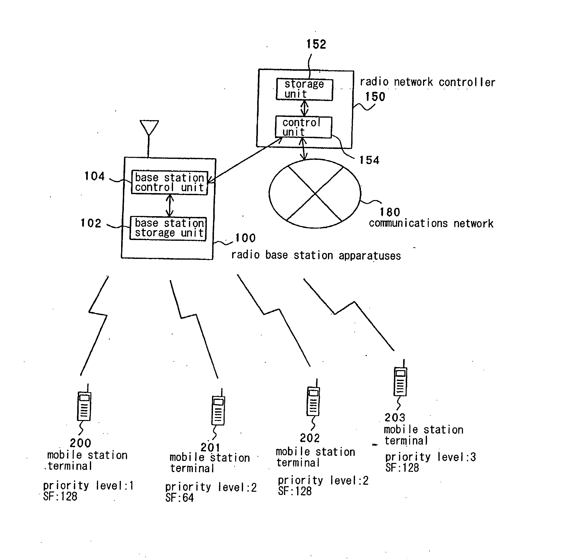
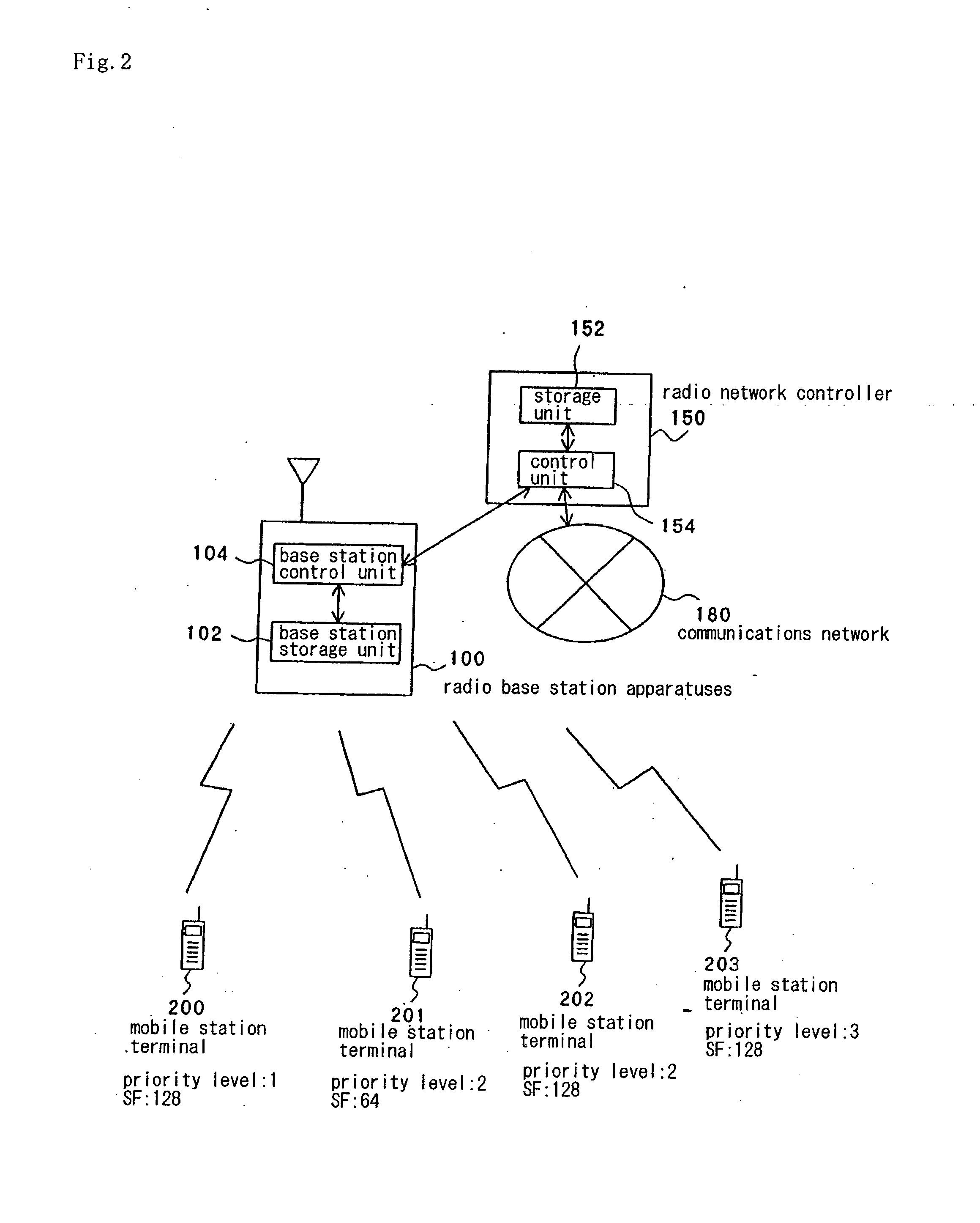
[0063]FIG. 2 is a block diagram illustrating an exemplary configuration of a communications system of this embodiment. Assume in this embodiment that the communications system employs a normal spread spectrum technology (CDMA: Code Division Multiple Access).

[0064] As illustrated in FIG. 2, the communications system comprises base station 100, and radio network controller 150 for controlling base station 100. Radio network controller 150 is connected to communications network 180 which serves as a telephone network. Base station 100 is connected to mobile station terminals 200-203 by radio communications. Base station 100 is installed every several tens of kilometers, and a cell is assigned to each base station 100.

[0065] It should be noted that while a plurality of base stations may be connected to radio network controller 150, there is one base station 100 in this embodiment in order to simplify the descr...

embodiment 2

[0115] In this embodiment, SF is utilized, in addition to the user's priority level, as a criterion for the base station to select a mobile station terminal which is subject to a forced termination of communication or a reduction in transmission power upper limit value. Since this embodiment is similar in configuration to Embodiment 1, a detailed description thereof is omitted.

[0116] A description will be given of a method for selecting a mobile station terminal for which the transmission power is controlled in this embodiment.

[0117] At step B2 and step B5 shown in FIG. 4, upon selection of the lowest prioritized user, base station control unit 104 references SF of each user if the priority level management table enumerates a plurality of users who are assigned the same priority level. As a result of referencing the SF's, base station control unit 104 selects a mobile station terminal of the user who presents the smallest SF for transmission power control processing.

[0118] Here, ...


PUM


Abstract

Radio base station apparatus 100 of the present invention monitors total transmission power which is the sum of transmission power for all mobile station terminals 200-203 connected for communication, reduces the upper limit of transmission power for the lowest prioritized mobile station terminal by a predetermined amount when the total transmission power exceeds a first threshold which is referenced to determine whether or not the transmission power has been reduced, and terminates communication with the lowest prioritized mobile station terminal when the total transmission power exceeds a second threshold which is larger than the first threshold.

Description

TECHNICAL FIELD [0001] The present invention relates to a radio base station apparatus which enables radio communications with mobile station terminals such as portable telephones, and a transmission power control method therefor. BACKGROUND ART [0002] Conventionally, in a communications system which employs mobile station terminals such as portable telephones, radio base station apparatuses (hereinafter called the “base station”) are provided for transmitting / receiving signals to / from mobile station terminals in order to enable communications with the mobile station terminals over the air within a coverage area which is an area in which communication services are provided. One base station is installed in every predetermined area such that a plurality of base stations cover the entire coverage area. An area covered by one base station is called a “cell.” A plurality of base stations are connected to a radio network controller which controls the base stations, and are connected to a...

Claims


Application Information

Patent Timeline
Patent Type & Authority Applications(United States)
IPC IPC(8): H04B7/00H04B1/38H04Q7/20H04B1/69H04B1/707H04B7/005H04B7/26H04W52/04H04W52/28H04W52/30H04W52/34H04W76/02
CPCH04B2201/70706Y02B60/50H04W52/346H04W52/281
Inventor TAKAGI, KENKIITO, KENICHIYASAKI, TAKAHIROMIKOSHIBA, TAKANORI
Owner NEC CORP
Learn More