
Electric steering device

a technology of electric steering and steering shaft, which is applied in mechanical devices, transportation and packaging, and gearing, etc., can solve the problems of large torque and relatively large friction coefficient of the nut loosening nuts, and achieve the effect of reducing the impact at the stop time and long permissible tim

Inactive Publication Date: 2007-08-09
NSK LTD
View PDF8 Cites 12 Cited by
  • Summary
  • Abstract
  • Description
  • Claims
  • Application Information

AI Technical Summary

Benefits of technology

[0010]An object of the present invention is to provide an electric steering device capable of surely loosening a nut without being tightened with large torque on the screw segment of a feeding screw shaft even when the nut or the column strikes with the securing portion of a moving end at the moving end of a tilting motion or telescopic motion.
[0018]According to a second invention, as set forth in the first aspect of the invention, it is preferable that the buffers abut on the column at a tilting ascent end or a tilting descent end of the column thereby to buffer an impact force when the column stops at the moving end of the column.
[0028]each of the buffers abuts on the sleeve at each of a telescopic advanced end or a telescopic retracted end of the inner column thereby to buffer an impact force when the sleeve stops at a moving end of the inner column.
[0037]Further, in the electric steering device according to the present invention, because of the presence of the buffer, a long permissible time can be taken until the nut or the column stops at the moving end. Therefore, also in the fail-safe function such as protective control of an excessive current, control is made so that the electric actuator stops within an elastic limit of the buffer. Thus, the impact at the time of stop can be alleviated. In addition, as regards the inconvenience of position control due to voltage shortage or pulse drift of a control signal, the operation of the electric actuator can be stopped while the impact is alleviated.

Problems solved by technology

When the nut thus tightened is loosened, however, the friction coefficient becomes relatively large because the friction at this time is static friction.
Therefore, large torque is required to loosen the nut which has struck with the securing portion and so has been tightened.

Method used


Image

  • Electric steering device
  • Electric steering device
  • Electric steering device

Examples


embodiment 1

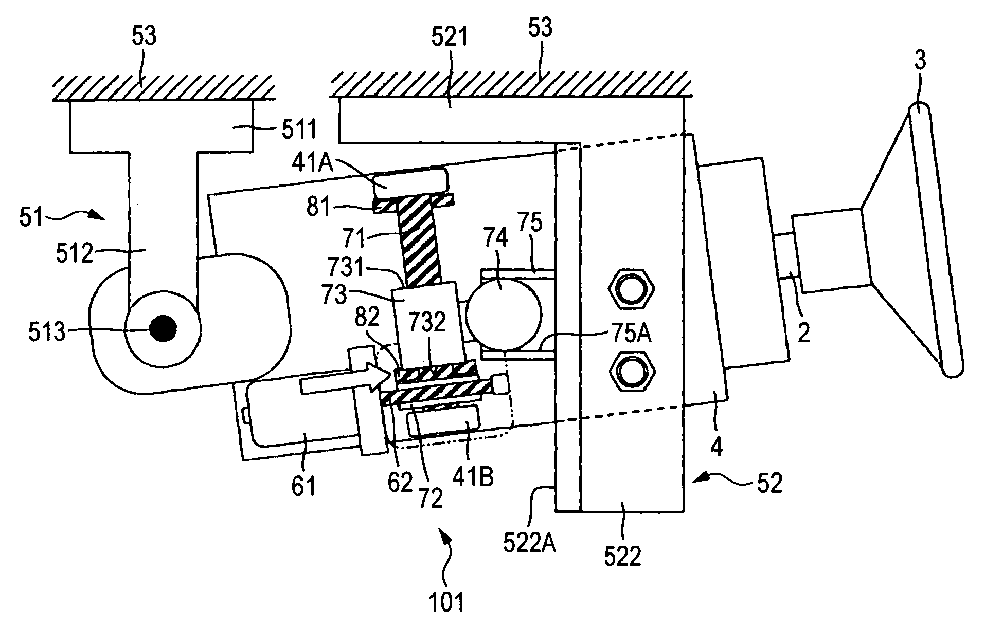
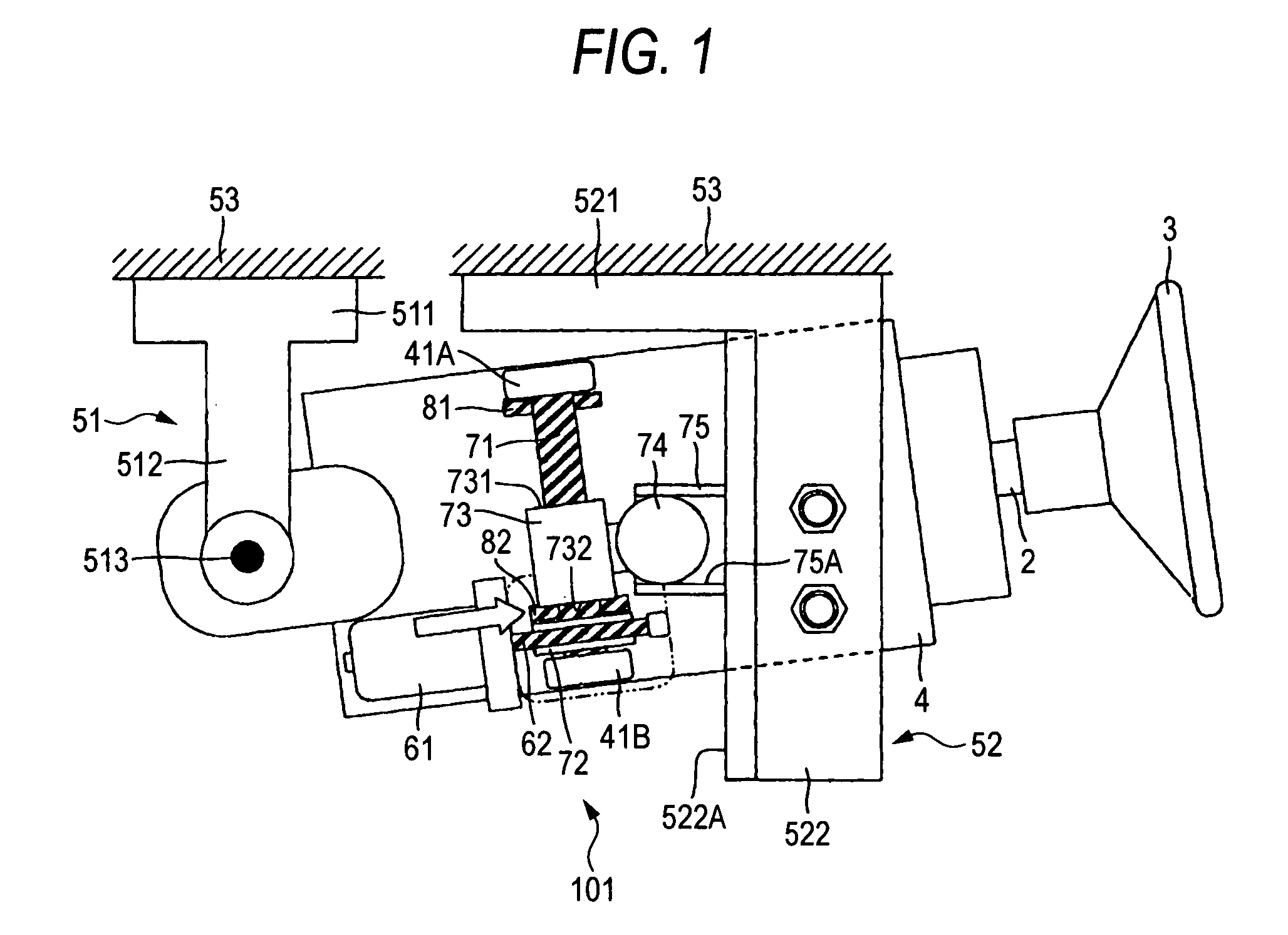
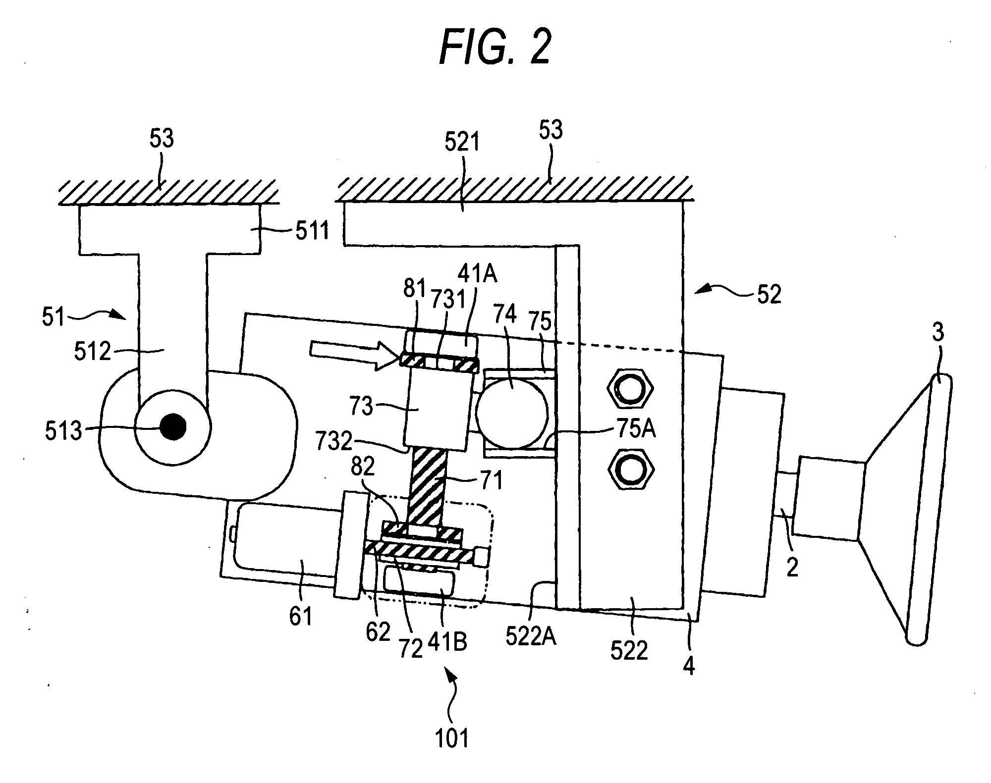
[0055]FIG. 1 is a schematic view of the main part including a partial section of an electric tilting steering device 101 according to the first embodiment of the present invention, which illustrates the state stopped at a tilting ascent end. FIG. 2 is a schematic view of the main part including a partial section of the electric tilting steering device 101 shown in FIG. 1, which shows the state stopped at a tilting descent end. FIG. 3 is a view of a buffer unit as a component; FIG. 3A is its longitudinal sectional view and FIG. 3B is a view seen along arrow P in FIG. 3A. FIG. 4 is a view of a modification of the buffer unit as a component; FIG. 4A is a longitudinal sectional view, FIG. 4B is a view seen along arrow Q in FIG. 4A and FIG. 4C is a longitudinal sectional view of a further modification of FIG. 4A.

[0056]On the left side of FIG. 1 (the forward side of a vehicle body), an attachment 511 formed at a top of a lower vehicle-body attaching bracket 51 which has a T-shape when see...

embodiment 2

[0071]Next, an explanation will be given of the second embodiment of the present invention. FIG. 5 is a schematic view of the main part including a partial section of an electric telescopic steering device 102 according to the second embodiment of the present invention, which illustrates the state stopped at a telescopic retracted end. FIG. 6 is a schematic view of the main part including a partial section of the electric telescopic steering device 102 shown in FIG. 5, which shows the state stopped at a telescopic advanced end. In the following explanation, only the structural portion different from the first embodiment will be explained and overlapping of the explanation will be avoided. Further, in this embodiment, like reference numerals refer to like elements in the first embodiment.

[0072]An inner column 43 is fit telescopic-slidably in an axial direction (horizontal direction in FIG. 5) in a hollow cylindrical outer column 42. On the bottom of the outer column 42, an opening 45...

embodiment 3

[0081]Next, an explanation will be given of the third embodiment of the present invention. FIG. 7 is a schematic view of the main part including a partial section of an electric tilting steering device 103 according to the third embodiment of the present invention, which illustrates the state stopped at a tilting ascent end. FIG. 8 is a schematic view of the main part including a partial section of the electric tilting steering device 103 shown in FIG. 7, which shows the state stopped at a tilting descent end. In the following explanation, only the structural portion different from the above embodiments will be explained and overlap of the explanation will be avoided. Further, in this embodiment, like reference numerals refer to like elements in the above embodiments.

[0082]In the first embodiment, the buffer is mounted on the outer circumferential surface of the feeding screw shaft 71. On the other hand, in the third embodiment, the buffer is mounted between the column 4 and an uppe...


PUM


Abstract

When a column 4 reaches a tilting ascent end, the lower end 732 of a nut 73 abuts on the buffering segment 83 of a buffer 82. Thus, while the buffering segment 83 of the buffer 82 is elastically deformed, the nut 73 stops with no impact. Accordingly, the inertia when the nut 73 stops is restrained and the tightening torque of the nut 73 when the nut 73 stops is also restrained. For this reason, when an electric motor 61 is rotationally driven in a reverse direction, a feeding screw shaft 71 rotates in the reverse direction with the normal rotation torque of the electric motor 61. Thus, the nut 73 is caused to ascend in the axial direction along the screw segment of the feeding screw shaft 71 so that the column 4 can be tiltingly moved downward.

Description

[0001]This application claims priority from Japanese Patent Application Nos. JP-2006-032580 and JP-2006-347157, filed on Feb. 9, 2006 and Dec. 25, 2006 in the Japanese Patent Office, the entire disclosure of which is incorporated herein by reference.BACKGROUND OF THE INVENTION[0002]1. Field of the Invention[0003]The present invention relates to an electric steering device, and more particularly to an electric steering device capable of adjusting a tilting position or a telescopic position of a steering wheel by an electric motor.[0004]2. Description of Related Art[0005]Recently, it has been required to adjust the tilting position and telescopic position of a steering wheel according to the physique and driving posture of a driver. For the purpose of facilitating the adjustment of the tilting position or telescopic position using an electric motor, mostly, an electric steering device has been adopted. Such an electric steering device is disclosed in for example PCT Publication WO03 / 0...

Claims


Application Information

Patent Timeline
Patent Type & Authority Applications(United States)
IPC IPC(8): B62D1/18
CPCY10T74/18688B62D1/181
Inventor TOMARU, MASAKITOMARU, YUUICHIYONEZAWA, KOUHEISAWADA, NAOKI
Owner NSK LTD
Learn More