
Disk device provided with tray

a technology of a tray and a disk device, which is applied in the field of disk devices, can solve the problems of significant deformation of the quality of the disk device, increased cost, abnormal sound or abrasion powder, etc., and achieves the effect of suppressing the generation of abnormal sound and abrasion powder, simple and low-cost structure, and suppressing the abrupt inclination of the tray

Inactive Publication Date: 2007-08-02
ORION ELECTRIC CO LTD
View PDF14 Cites 2 Cited by
  • Summary
  • Abstract
  • Description
  • Claims
  • Application Information

AI Technical Summary

Benefits of technology

[0008]The present invention has been implemented in view of the above described problems and it is an object of the present invention to provide a disk device provided with a tray having a simple and low-cost structure, capable of effectively suppressing an abrupt inclination of the tray and suppressing the generation of abnormal sound and abrasion powder or the like when moving the tray.
[0009]The disk device provided with a tray according to a first aspect of the present invention is a disk device provided with a tray including a tray on which a disk-shaped storage medium is mounted, a frame which supports the tray and guiding means for guiding the tray between a disk loading / unloading position and a disk reproducing position in a manner freely movable back and forth, wherein the frame is provided with inclination relaxation means for suppressing an abrupt inclination of the tray which occurs when the tray is carried out of the frame and moved.
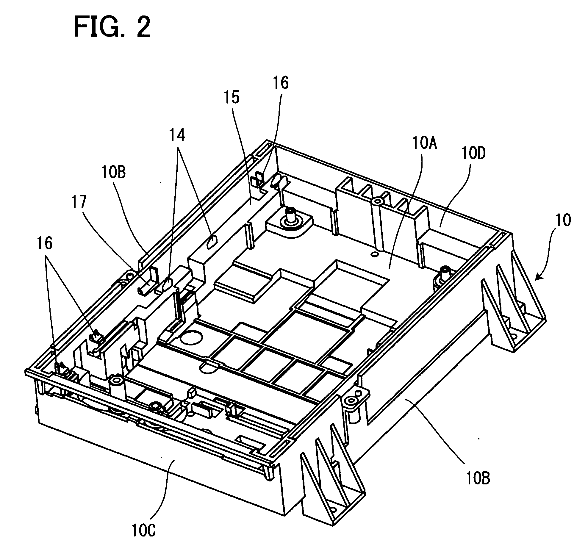
[0011]The disk device provided with a tray according to a second aspect of the present invention is the disk device provided with a tray according to the first aspect of the present invention, wherein the frame is provided with a horizontal plane which guides the tray and side walls integrally formed on both left and right sides of the horizontal plane, the guide means comprises guide rails formed in undersides of both edges of the tray and engaging projections which protrude from the horizontal plane and engage with recessed grooves of the guide rails, and a plurality of guide ribs are integrally formed on inner surfaces of the side walls of the frame so as to contact top surfaces of the guide rails and suppress floating of the tray.
[0012]According to the second aspect of the present invention, when moving the tray through the drive mechanism, the engaging projections which protrude from the horizontal planes of the frame engage with the recessed grooves formed in the guide rails of the tray and the tray is moved along the engaging projections from the disk loading / unloading position to the disk reproducing position or from the disk reproducing position to the disk loading / unloading position. At this time, the plurality of guide ribs formed on inner sides of the side walls of the frame contact the top surfaces of the guide rails and the guide ribs suppress floating of the tray.
[0016]According to the fourth aspect of the present invention, when the center of gravity of the tray is located between a part of the tray which protrudes from the frame and another part of the tray inside the frame, the top surface of the back part of the tray contacts the inclination relaxation ribs thereby suppressing such a fluctuation that the tray abruptly inclines. Furthermore, the inclination relaxation ribs also function as the guide ribs to suppress floating of the tray.

Problems solved by technology

However, when the tray which is carried out and moved from the disk reproducing position to the disk loading / unloading position protrudes farther than when the center of gravity of the tray is located between a part of the tray which protrudes from the frame and another part of the tray inside the frame, the tray inclines abruptly by the own weight of the tray which protrudes from the frame, which constitutes a factor for causing the quality of the disk device to significantly degrade.
The disk device described in patent document 1 makes the pushing piece formed in the top plate elastically contact the top surface of the tray to suppress the inclination of the tray in the vertical direction, at the same time makes the U-shaped arc surface formed in the frame elastically contact the guide grooves of the tray so as to suppress backlash of the tray in the horizontal direction, and therefore pushing forces of the pushing piece while the tray moves and the arc surface are always applied to the tray and excessive contact with the pushing piece and the arc surface may cause friction and produce abnormal sound or abrasion powder or the like.
Furthermore, molding and working on the pushing piece and arc surface is also complicated, resulting in a problem of causing an increase in cost.

Method used


Image

  • Disk device provided with tray
  • Disk device provided with tray
  • Disk device provided with tray

Examples


Embodiment Construction

[0032]Hereinafter, a specific embodiment of the present invention will be explained with reference to attached drawings. It should be noted that the following embodiment is a mode of implementing the present invention and is by no means intended to confine the present invention within the scope thereof.

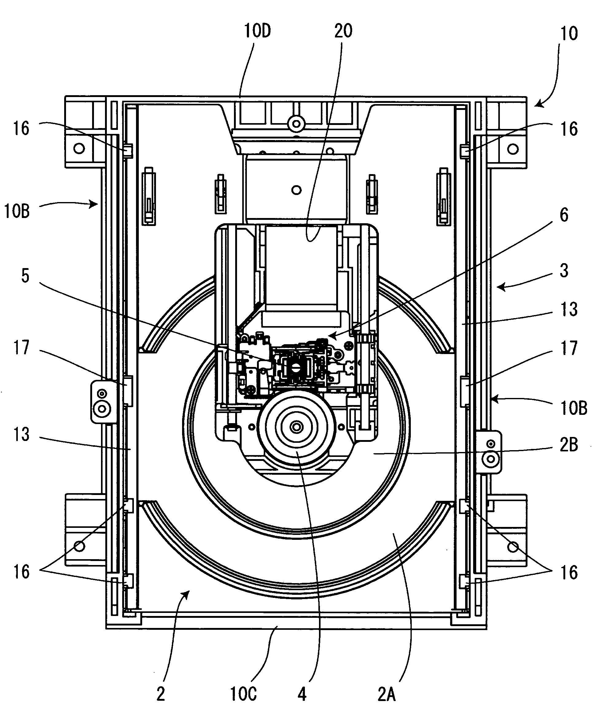
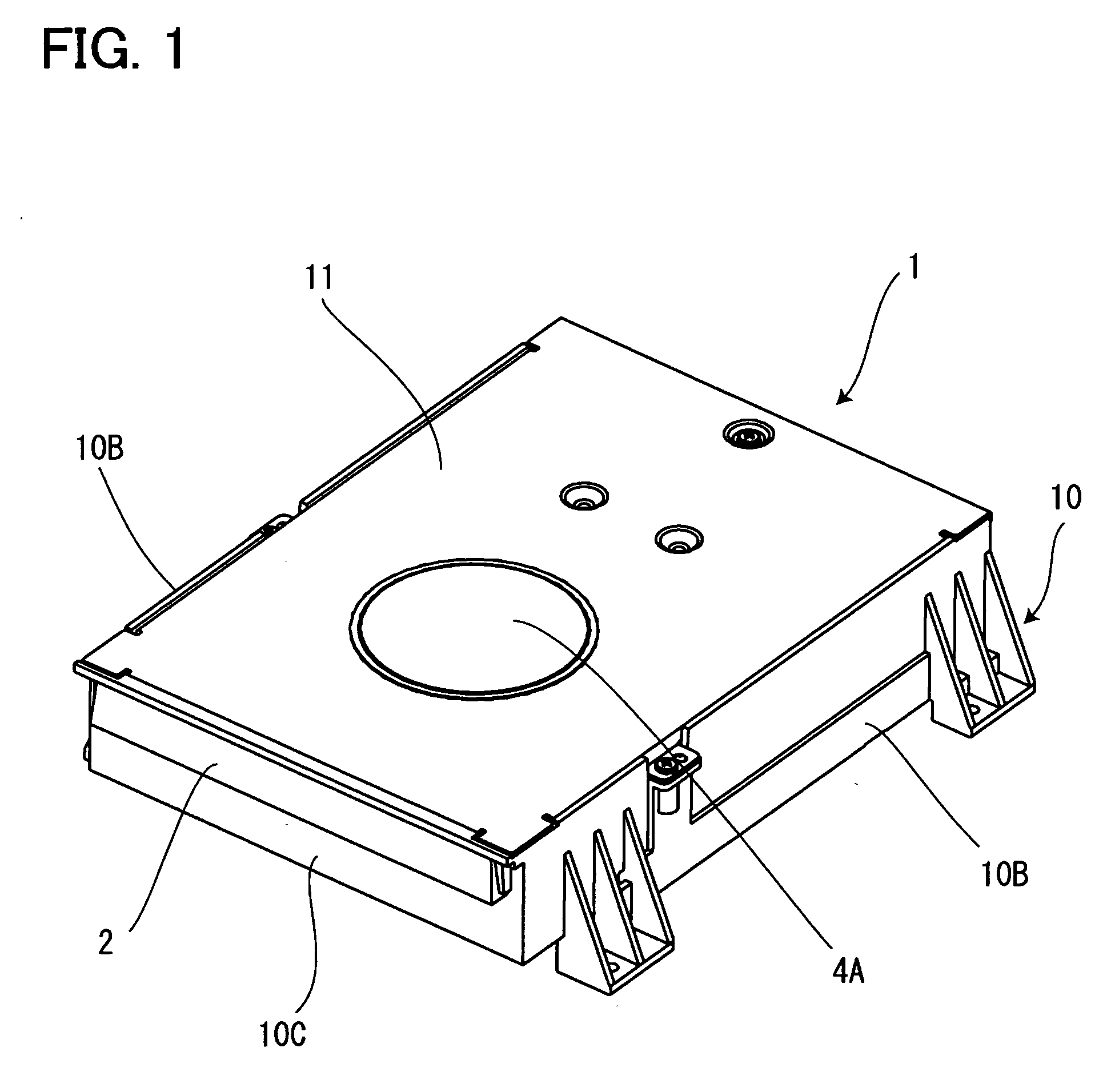
[0033]FIG. 1 to FIG. 11 show an embodiment of the present invention, FIG. 1 is a perspective view of a disk device showing an embodiment of the present invention, FIG. 2 is a perspective view showing a frame as a single unit, FIG. 3 is a plan view showing the frame as a single unit, FIG. 4 is a cross-sectional view showing the frame as a single unit, FIG. 5 is a perspective view showing a tray as a single unit, FIG. 6 shows a plan view and a back view showing the tray as a single unit, FIG. 7 is a perspective view of the disk device showing a state in which the cover has been removed, FIG. 8 is a plan view of the disk device in a state in which the cover has been removed at the disk r...


PUM


Abstract

A disk device provided with a tray capable of suppressing an abrupt inclination of the tray and moving the tray in a stable condition is provided. When moving the tray 2 from a disk reproducing position to a disk loading / unloading position, the tray 2 becomes most unstable when a position of the center of gravity S of the tray 2 reaches a front wall 10C of a frame 10, but making an inclination relaxation rib 17 contact a top surface of the back end of a guide rail 13 at the position causes the tray 2 to move without abruptly inclining.

Description

[0001]The present application is based on and claims priority of Japanese patent application No. 2006-020787 filed on Jan. 30, 2006, the entire contents of which are hereby incorporated by reference.BACKGROUND OF THE INVENTION[0002]1. Field of the Invention[0003]The present invention relates to a disk device which guides a disk-shaped storage medium (hereinafter, simply referred to as a “disk”) between a disk loading / unloading position and a disk reproducing position in a manner freely movable back and forth and records or reproduces the disk at the disk reproducing position, and more particularly, to a disk device which can suppress an abrupt inclination of the tray which occurs when the tray is carried out of the disk reproducing position and moved.[0004]2. Description of the Related Art[0005]Conventionally, a disk device which records or reproduces data onto / from a disk is not limited to a stationary DVD player and a CD player or the like, but the application thereof extends over...

Claims


Application Information

Patent Timeline
IPC IPC(8): G11B17/04G11B33/02
CPCG11B17/056
Inventor MAKINO, TAKESHI
Owner ORION ELECTRIC CO LTD
Learn More