
Variable rate speech coding

a variable rate and speech technology, applied in the field of variable rate speech coding, can solve the problems of reducing the data rate required for satisfactory speech reproduction, reducing bit rate often exceeding the available bandwidth, etc., and achieves the effects of low bit rate, greater range, and higher capacity

Inactive Publication Date: 2007-08-02
QUALCOMM INC
View PDF9 Cites 19 Cited by
  • Summary
  • Abstract
  • Description
  • Claims
  • Application Information

AI Technical Summary

Benefits of technology

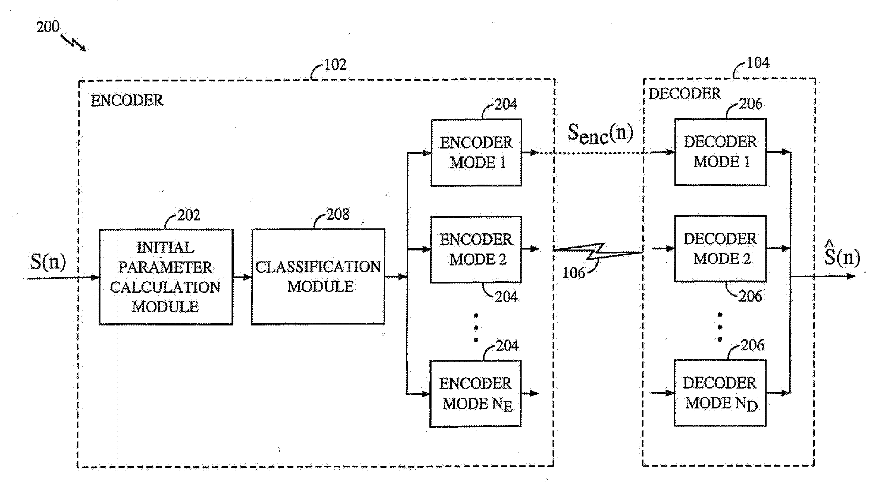
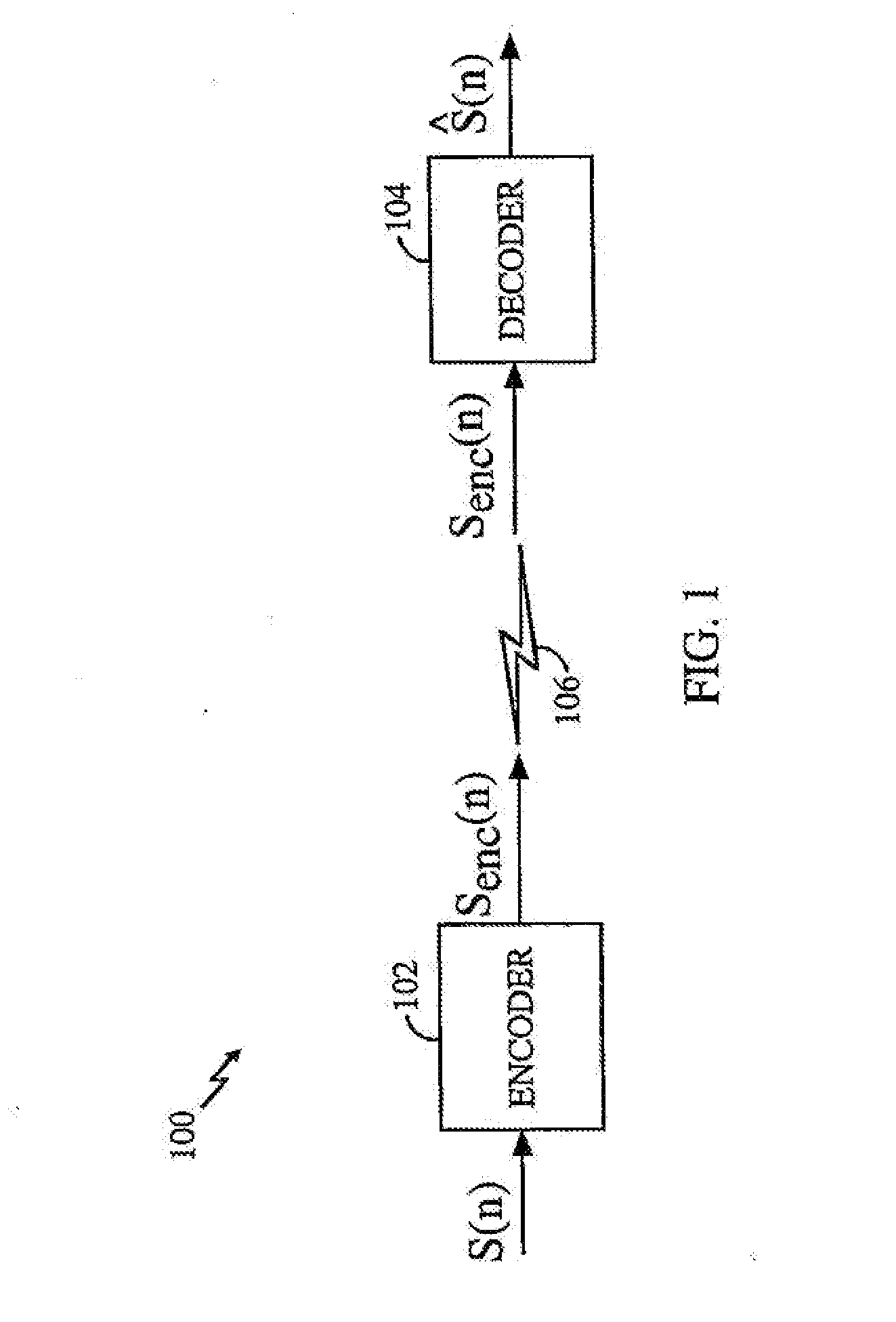
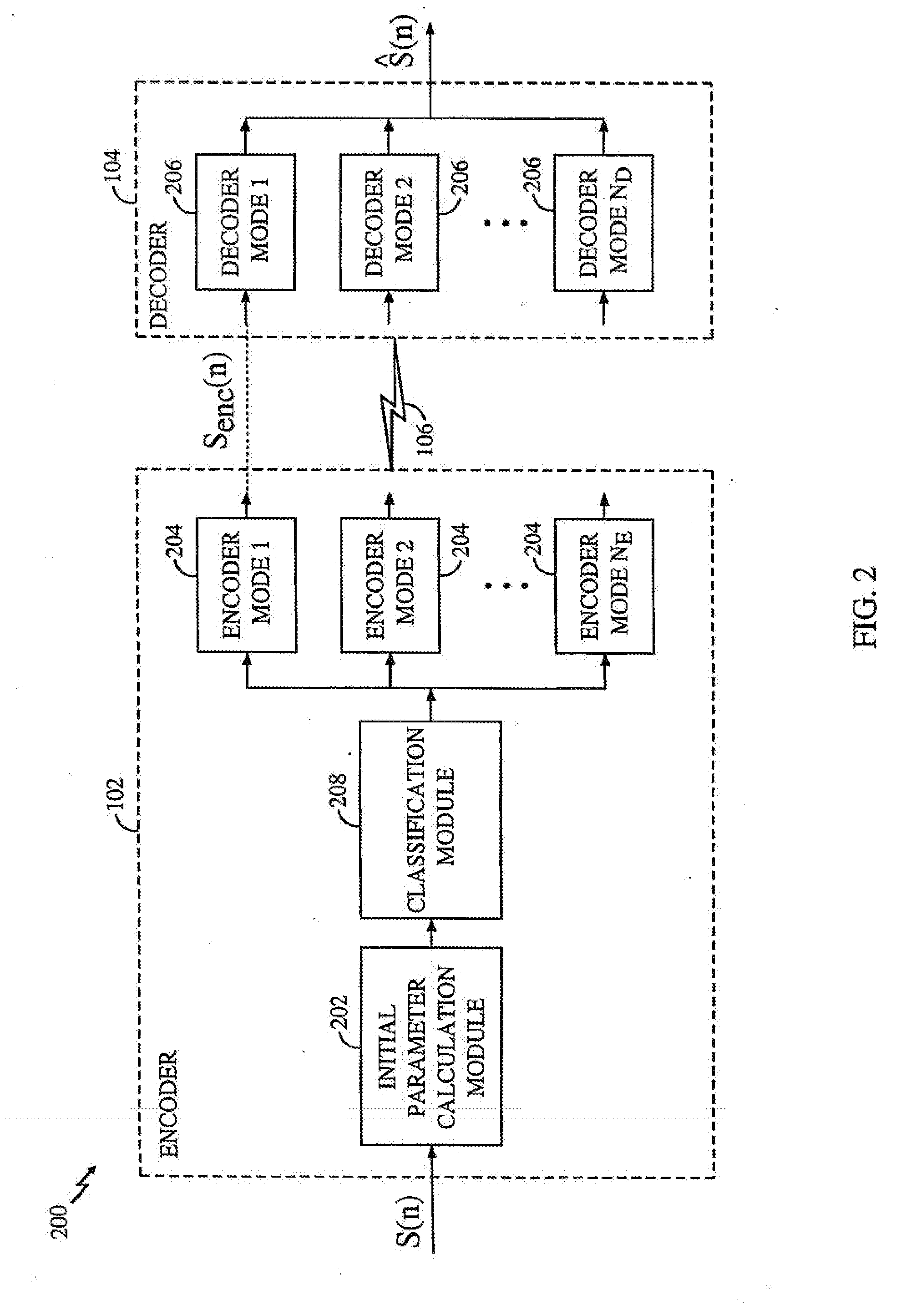
The present invention is a method and apparatus for coding speech signals using variable rates. The invention classifies the speech signal and selects an appropriate coding mode based on this classification. The invention achieves low average bit rates by only employing high fidelity modes during portions of speech where this fidelity is required for acceptable output. The invention switches to lower bit rate modes during portions of speech where these modes produce acceptable output. The invention can apply various coding modes to different types of active speech, depending upon the required level of fidelity. The invention dynamically switches between these modes as properties of the speech signal vary with time. The invention uses this coding in a dynamic fashion whenever unvoiced speech or background noise is detected. The technical effects of the invention are low bit rates, higher capacity, greater range, and lower power requirements.

Problems solved by technology

However, coding techniques are available that significantly reduce the data rate required for satisfactory speech reproduction.
However, even these reduced bit rates often exceed the available bandwidth where the speech signal must either propagate a long distance (e.g., ground to satellite) or coexist with many other signals in a crowded channel.

Method used


Image

  • Variable rate speech coding
  • Variable rate speech coding
  • Variable rate speech coding

Examples


Embodiment Construction

[0046] I. Overview of the Environment [0047] II. Overview of the Invention [0048] III. Initial Parameter Determination [0049] A. Calculation of LPC Coefficients [0050] B. LSI Calculation [0051] C. NACF Calculation [0052] D. Pitch Track and Lag Calculation [0053] E. Calculation of Band Energy and Zero Crossing Rate [0054] F. Calculation of the Formant Residual [0055] I. Active / Inactive Speech Classification [0056] A. Hangover Frames [0057] I. Classification of Active Speech Frames [0058] II. Encoder / Decoder Mode Selection [0059] III. Code Excited Linear Prediction (CELP) Coding Mode [0060] A. Pitch Encoding Module [0061] B. Encoding codebook [0062] C. CELP Decoder [0063] D. Filter Update Module [0064] I. Prototype Pitch Period (PPP) Coding Mode [0065] A. Extraction Module [0066] B. Rotational Correlator [0067] C. Encoding Codebook [0068] D. Filter Update Module [0069] E. PPP Decoder [0070] F. Period Interpolator [0071] I. Noise Excited Linear Prediction (NELP) Coding Mode [0072] II. ...


PUM


Abstract

A method and apparatus for the variable rate coding of a speech signal. An input speech signal is classified and an appropriate coding mode is selected based on this classification. For each classification, the coding mode that achieves the lowest bit rate with an acceptable quality of speech reproduction is selected. Low average bit rates are achieved by only employing high fidelity modes (i.e., high bit rate, broadly applicable to different types of speech) during portions of the speech where this fidelity is required for acceptable output. Lower bit rate modes are used during portions of speech where these modes produce acceptable output. Input speech signal is classified into active and inactive regions. Active regions are further classified into voiced, unvoiced, and transient regions. Various coding modes are applied to active speech, depending upon the required level of fidelity. Coding modes may be utilized according to the strengths and weaknesses of each particular mode. The apparatus dynamically switches between these modes as the properties of the speech signal vary with time. And where appropriate, regions of speech are modeled as pseudo-random noise, resulting in a significantly lower bit rate. This coding is used in a dynamic fashion whenever unvoiced speech or background noise is detected.

Description

RELATED APPLICATIONS [0001] This application is a continuation of U.S. application Ser. No. 10 / 713,758, filed Nov. 14, 2003 now U.S. Pat. No. 7,136,812, issued Nov. 14, 2006 which is entitled “Variable Rate Speech Coding,” and currently assigned to the assignee of the present application and which is a continuation of U.S. application Ser. No. 09 / 217,341, filed Dec. 21, 1998, now U.S. Pat. No. 6,691,084, issued Feb. 10, 2004 which is entitled “Variable Rate Speech Coding,” and currently assigned to the assignee of the present application.BACKGROUND OF THE INVENTION [0002] 1. Field of the Invention [0003] The present invention relates to the coding of speech signals. Specifically, the present invention relates to classifying speech signals and employing one of a plurality of coding modes based on the classification. [0004] 2. Description of the Related Art [0005] Many communication systems today transmit voice as a digital signal, particularly long distance and digital radio telephon...

Claims


Application Information

Patent Timeline
Patent Type & Authority Applications(United States)
IPC IPC(8): G10L19/00G10L19/18G10L11/02G10L19/04G10L19/14G10L19/24G10L25/90G10L25/93H03M7/30
CPCG10L19/20G10L2025/935G10L2025/783G10L19/24G10L19/18
Inventor MANJUNATH, SHARATHGARDNER, WILLIAM
Owner QUALCOMM INC
Learn More