
Light emitting diode module

a technology of light-emitting diodes and led modules, which is applied in the direction of textile articles, semiconductor devices, ornamental textile articles, etc., can solve the problems of low light extraction efficiency and decrease in the luminous efficiency of led modules, and achieve the effect of high luminous efficiency

Active Publication Date: 2007-08-02
SAMSUNG ELECTRONICS CO LTD
View PDF6 Cites 33 Cited by
  • Summary
  • Abstract
  • Description
  • Claims
  • Application Information

AI Technical Summary

Benefits of technology

The present invention is about a LED module that has a structure that can emit light with high efficiency. The LED module includes a light emitting chip, a layer of phosphor materials that emits light with a longer wavelength than the light emitted from the chip, and a reflection plate that is placed between the chip and the phosphor layer. The reflection plate reflects the light emitted from the phosphor layer. This structure helps to increase the amount of light that is emitted from the LED module.

Problems solved by technology

However, in the configuration described above, the light extraction efficiency is low.
Accordingly, light that is not fully emitted outward and is instead emitted in the downward direction of FIG. 2 is thus counted as loss resulting in a decrease in the luminous efficiency of the LED module.

Method used


Image

  • Light emitting diode module
  • Light emitting diode module
  • Light emitting diode module

Examples


Embodiment Construction

[0018]The present invention will now be described more fully with reference to the accompanying drawings, in which exemplary embodiments of the invention are shown.

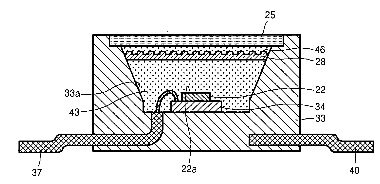
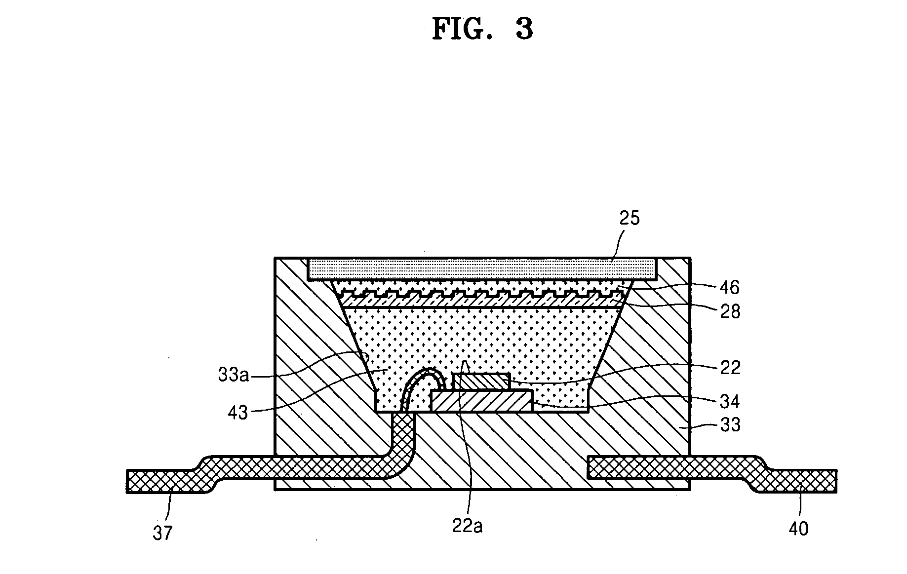
[0019]FIG. 3 is a cross-sectional view of an LED module according to an embodiment of the present invention; and FIGS. 4A through 4D illustrate a number of reflection plates according to various embodiments of the present invention.

[0020]Referring to FIG. 3, the LED module includes a light emitting chip 22, a phosphor layer 25 using the light emitted from the light emitting chip 22 as an excitation source and emitting light of a longer wavelength than the light emitted from the light emitting chip 22, and a reflection plate 28 that is disposed between the phosphor layer 25 and the light emitting chip 22 and reflects the light emitted in the downward direction of FIG. 3 by the excited phosphor layer 25.

[0021]The light emitting chip 22 is disposed on a submount 34 that is mounted in a dispensing member 33 having a cup-shape...


PUM


Abstract

A light emitting diode module having improved luminous efficiency is provided. The light emitting diode module includes: a light emitting chip; a phosphor layer formed of phosphor materials emitting light having a wavelength longer than the light emitted from the light emitting chip using light emitted from the light emitting chip as an excitation source; and a reflection plate that is disposed between the light emitting chip and the phosphor layer and that reflects the light emitted by the phosphor layer.

Description

CROSS-REFERENCE TO RELATED PATENT APPLICATION[0001]This application claims the benefit of Korean Patent Application No. 10-2006-0010179, filed on Feb. 2, 2006 in the Korean Intellectual Property Office, the disclosure of which is incorporated herein in its entirety by reference.BACKGROUND OF THE DISCLOSURE[0002]1. Field of the Disclosure[0003]The present disclosure relates to a light emitting diode module, and more particularly, to a light emitting diode module with an improved structure providing an improved luminous efficiency for realizing white light or colored light while using a light emitting diode emitting blue or ultraviolet light and phosphor materials.[0004]2. Description of the Related Art[0005]A light emitting diode (LED) is formed of a light emitting source using compound semiconductors, such as GaAS, AlGaN, and AlGaAs, to generate various colors of light. LEDs can be easily manufactured and controlled compared to semiconductor lasers and have longer life spans than fl...

Claims


Application Information

Patent Timeline
Patent Type & Authority Applications(United States)
IPC IPC(8): H01L33/00H01L33/22H01L33/50H01L33/60
CPCH01L33/50H01L33/46D04D9/00D07B9/00
Inventor KIM, YU-SIKKIM, HYUNG-KUNSONE, CHEOL-SOOJEONG, JAE-WOOK
Owner SAMSUNG ELECTRONICS CO LTD
Learn More