
Filtration architecture for optimized performance

a technology of filtration architecture and filter bag, applied in the direction of filtration separation, chemistry apparatus and processes, separation processes, etc., can solve the problems of ineffective filter bags, inefficient fluid distribution over the filtering medium, and decreased fluid flow rate through the filter bag

Active Publication Date: 2007-08-02
MECHANICAL MFG
View PDF28 Cites 32 Cited by
  • Summary
  • Abstract
  • Description
  • Claims
  • Application Information

AI Technical Summary

Benefits of technology

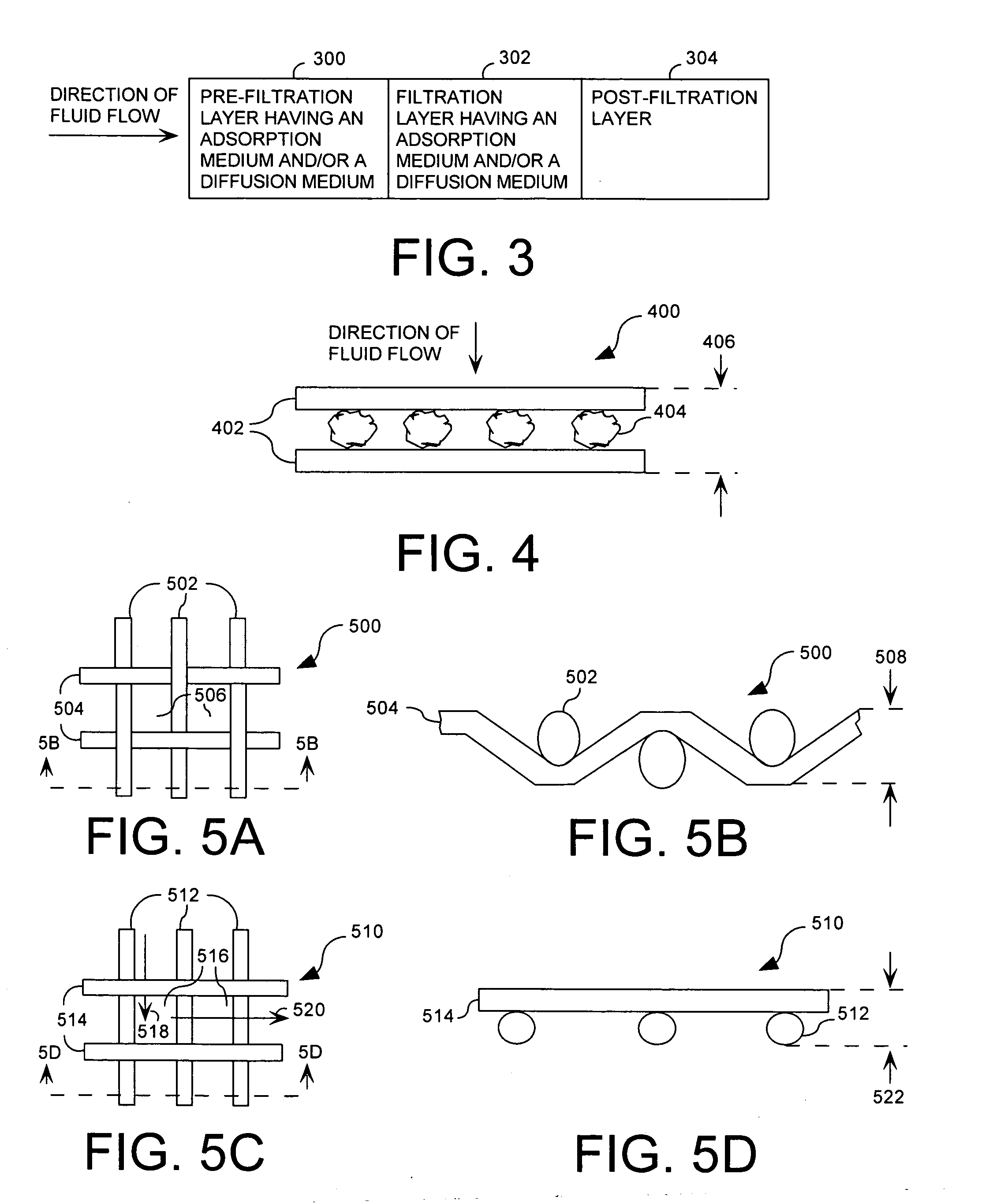
[0008] The invention concerns a filter bag for use in a liquid filtering system. The filter bag can comprise a filtration layer. The filtration layer can be defined by one or more filter mediums. The filter mediums can be defined by an adsorbent material disposed between two or more thin wall substrates. According to an embodiment of the invention, the adsorbent material can be a granular activated carbon. The thin wall substrates can be highly porous thin wall substrates.
[0009] According to another embodiment of the invention, the filtration layer can be further defined by one or more diffusion mediums. The diffusion mediums can be made from a suitable material that is temperature and fluid compatible with a filtering application to be carried out. For example, the diffusion medium can comprise a thermoplastic having polypropylene, nylon, or polyester. The diffusion medium can be defined by a woven or non-woven mesh material.
[0010] According to another embodiment of the invention, the filtration layer can be defined by alternating layers of medium including one or more filter mediums and one or more diffusion mediums. The filter mediums and the diffusion mediums can be joined using ultrasonic welding.
[0011] According to another embodiment of the invention, the filter bag can further comprise a pre-filtration layer. The pre-filtration layer can be defined by one or more pre-filtering mediums. The pre-filtering mediums can be defined by an adsorbent material disposed between two or more thin wall substrates. The adsorbent material can be a granular activated carbon.
[0012] According to another embodiment of the invention, the pre-filtering mediums can be further defined by one or more diffusion mediums. The diffusion mediums can be defined by a mesh material. The mesh material can be a woven or a non-woven mesh material. According to another embodiment of the invention, the pre-filtration layer can be defined by alternating layers of medium including one or more pre-filtering mediums and one or more diffusion mediums.

Problems solved by technology

Filter bags having a multi-layer filter structure typically become ineffective when contaminants are primarily collected at one layer.
When contaminants are primarily collected at one layer, an inefficient fluid distribution over the filtering medium results.
Also contributing to inefficiency is the decrease in the fluid flow rate through the filter bag.

Method used


Image

  • Filtration architecture for optimized performance
  • Filtration architecture for optimized performance
  • Filtration architecture for optimized performance

Examples


Embodiment Construction

[0024]FIG. 1 is a perspective view of a conventional filter bag including a filter material affixed to a ring member. A contaminated fluid is typically pumped into the filter bag 100 through the input orifice 104. The fluid flows through the filter bag 100 to produce a filtered fluid.

[0025] The filter bag 100 includes a bag member 102 and a ring member 106. The bag member 102 is composed of a filter material. The filter material typically comprises one or more layers of filtering medium having a number of pores to control fluid flow. The filtering medium is selected to comprise a material that is suitable for a particular filtration application, such as a micro-fiber (e.g. a polyester, polypropylene, fiberglass, polyamide, or fluorocarbon) or a monofilament (e.g. a nylon or a polypropylene monofilament). The filter material typically comprises an identical pore structure, a graded pore structure, or a tapered pore structure. A tapered or graded pore structure provides a filter mate...


PUM

PropertyMeasurementUnit
thicknessaaaaaaaaaa
sizeaaaaaaaaaa
thicknessaaaaaaaaaa

Abstract

A filter bag for use in a liquid filtering system is provided. The filter bag comprises a filtration layer. The filtration layer is defined by one or more filter mediums. The filter mediums can be composed of an adsorbent material disposed between two thin wall substrates. The adsorbent material can be a granular activated carbon. The thin wall substrates can be selected to be highly porous thin wall substrates. The filter bag can further comprise one or more diffusion mediums. The diffusion mediums can be defined by a woven or a non-woven mesh material. The mesh material can be selected from a suitable material that is temperature and fluid compatible with the filtering application to be carried out. The filter bag can include alternating layers of medium having one or more filter mediums and one or more diffusion mediums.

Description

BACKGROUND OF THE INVENTION [0001] 1. Statement of the Technical Field [0002] The invention concerns filtration equipment, specifically, filter bags used for such acts as removing organic contaminants, color, odor, or even chlorination from fluids. [0003] 2. Description of the Related Art [0004] A filter typically consists of a cartridge or a bag for use in a pressurized filter system. A pressurized filter system utilizing filter bags is typically comprised of a filter housing having a body and a cover. The body contains a filter basket for placing the filter bag therein. The filter housing is comprised of a mounting stand, an input orifice, and an output orifice. A contaminated fluid is pumped into the filter housing through the input orifice. The contaminated fluid is filtered as it flows through the filter bag and then exists through the output orifice. Such a pressurized filter system is disclosed in U.S. Pat. No. 5,246,581. [0005] A filter bag is typically composed of one or mo...

Claims


Application Information

Patent Timeline
Patent Type & Authority Applications(United States)
IPC IPC(8): B01D29/00
CPCB01D29/27
Inventor GOLDMAN, MICHAEL A.
Owner MECHANICAL MFG
Learn More