
Automatic spraying method for flux of wave solder oven

Inactive Publication Date: 2007-07-26
DELTA ELECTRONICS INC
View PDF2 Cites 15 Cited by
  • Summary
  • Abstract
  • Description
  • Claims
  • Application Information

AI Technical Summary

Benefits of technology

[0011] performing a parameter reading step to calculate control parameters for matching the PCB according to the first set parameter and the second set paramet

Problems solved by technology

However, the above-mentioned sensor arranged in the processing machine can only be useful for PCB of a single size (single length and width) and sends the sensed result externally.
This procedure is troublesome.

Method used


Image

  • Automatic spraying method for flux of wave solder oven
  • Automatic spraying method for flux of wave solder oven
  • Automatic spraying method for flux of wave solder oven

Examples


Embodiment Construction

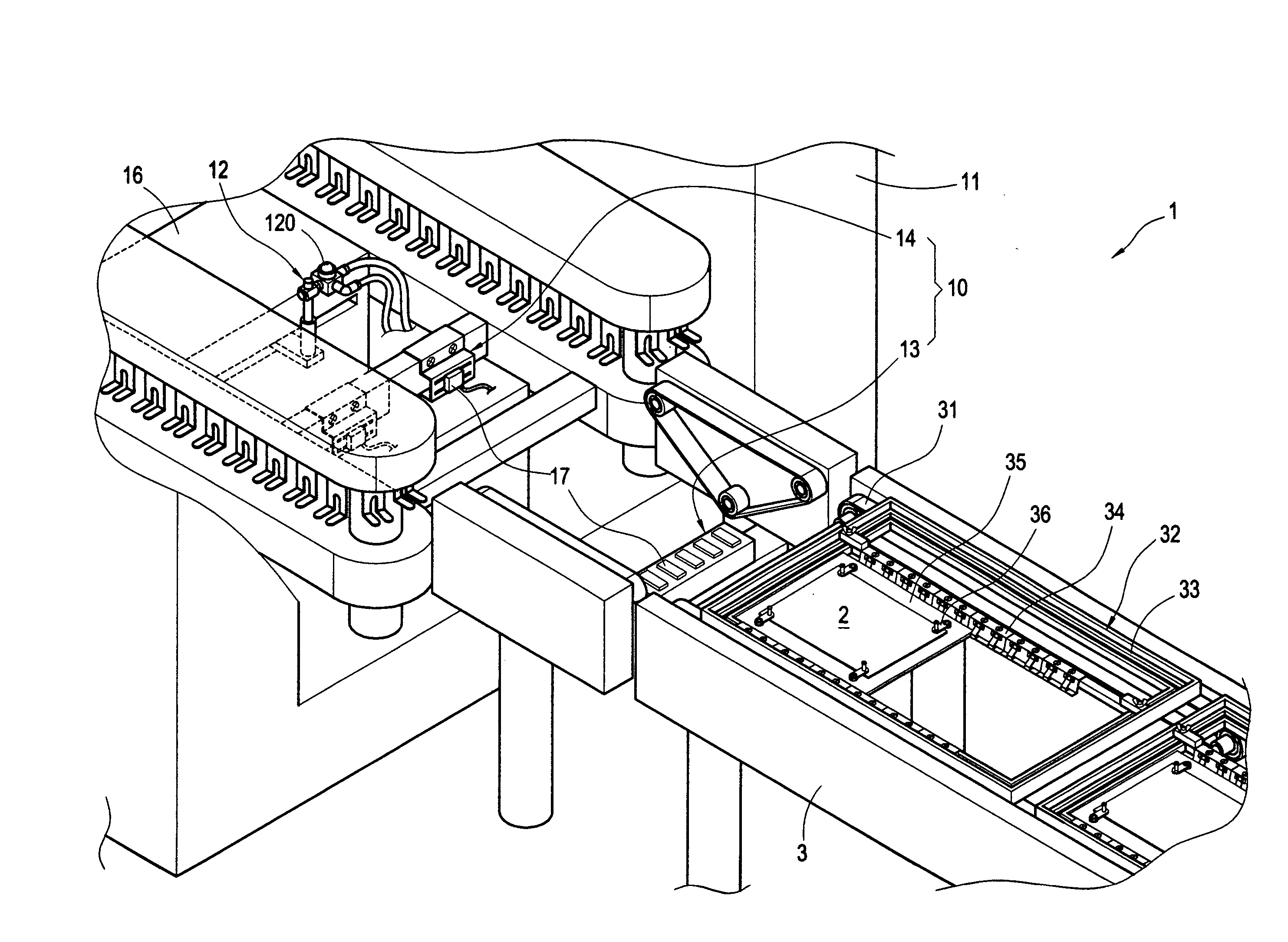
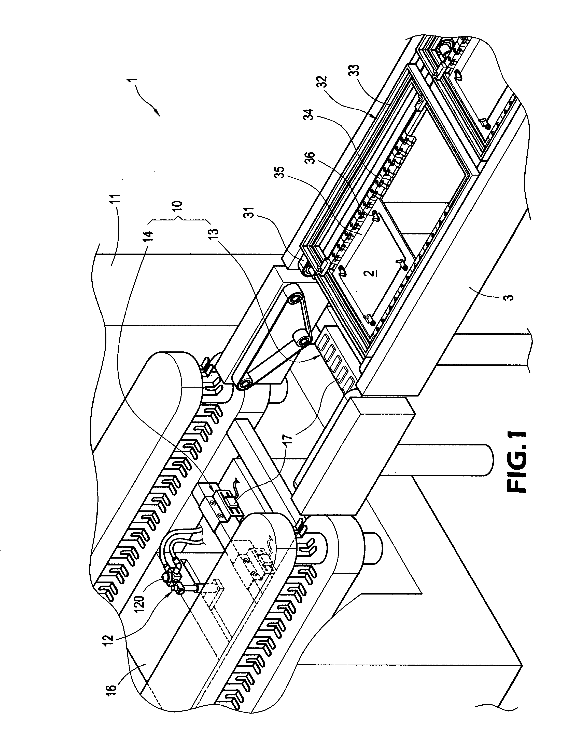
[0017] With reference to FIGS. 1 to 3, the automatic spraying apparatus for flux comprises a machine 1 with a cabinet 11, and a spray gun unit 12 and a sensor device 10 arranged in the cabinet 11. A convey unit 3 is connected to one end of the cabinet 11 for conveying the PCB to be processed to the cabinet 11 for applying the flux.

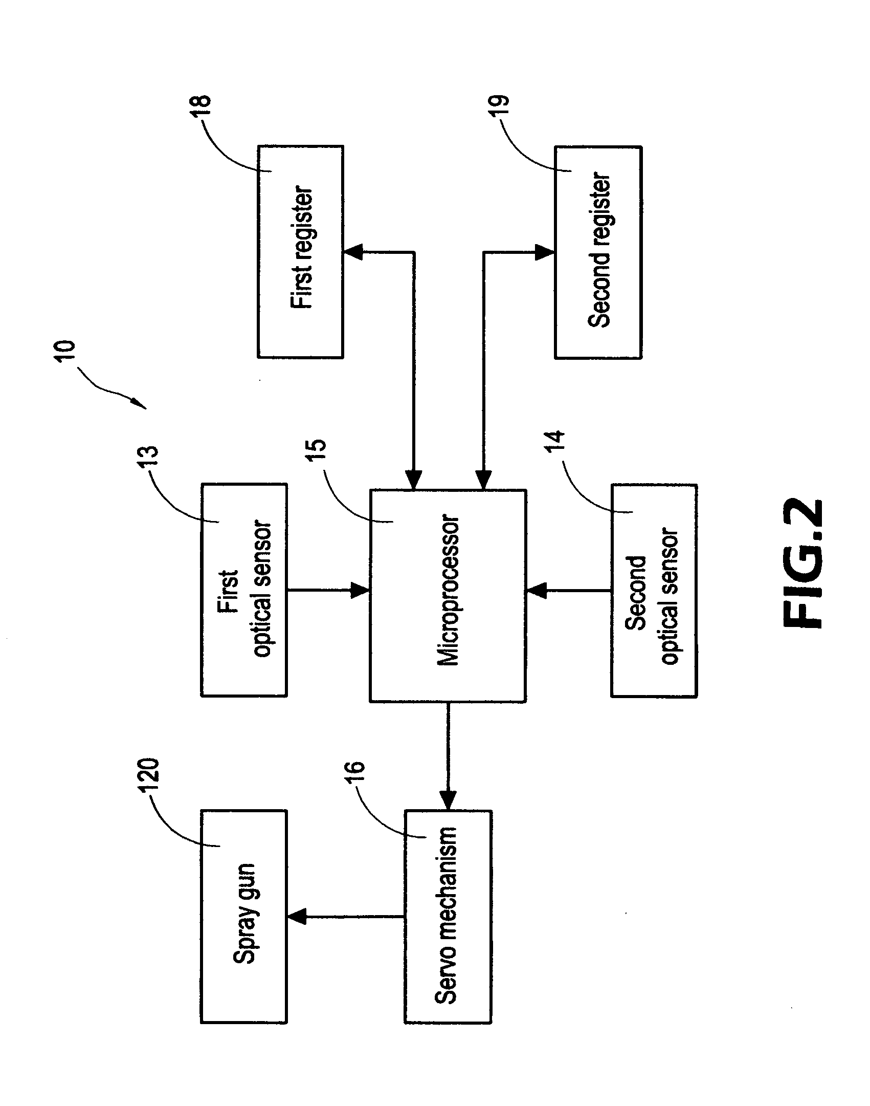
[0018] The sensor device 1 includes a first optical sensor 13, a second optical sensor 14 and a microprocessor 15. The microprocessor 15 is connected to a servo mechanism 16 of the spray gun unit 12.

[0019] The spray gun unit 12 comprises a spray gun 120 and the servo mechanism 16 for moving the spray gun 120.

[0020] The first optical sensor 13 and the second optical sensor 14 comprise a plurality of photo sensors 17 and arranged at two predetermined front positions of the spray gun unit 12 in predetermined separation. The first optical sensor 13 and the second optical sensor 14 are electrically connected to a first register 18 and a second register 19. T...


PUM

PropertyMeasurementUnit
Lengthaaaaaaaaaa
Speedaaaaaaaaaa
Widthaaaaaaaaaa

Abstract

An automatic spraying method is used for spraying flux of wave solder oven. A first optical sensor senses the width of a printed circuit board (PCB) to obtain a first set parameter, and the first set parameter is stored in an address designated by a first register. A second optical sensor senses the length, the width and the spraying direction of the PCB to obtain a second set parameter, and the second set parameter is stored in an address designated by a second register. The control parameters such as initial spraying position, spraying area and spraying speed are calculated with reference to the first and the second sets parameters. The flux is sprayed on the PCB by a spray gun according to the control parameters.

Description

BACKGROUND OF THE INVENTION [0001] 1. Field of the Invention [0002] The present invention relates to an automatic spraying method used for flux of wave solder oven, especially to an automatic spraying method sensing two spray parameters for PCB of various sizes and calculating the spray area and optimal spray control. [0003] 2. Description of Prior Art [0004] The conventional method for spraying the flux on printed circuit board (PCB) uses wave solder oven and a transmission unit. The PCB is conveyed to a processing machine and a plurality of sensors arranged in the processing machine sense the length and width of the PCB. The sensed result is used as control parameters for the spraying gun and the servo mechanism. The spraying gun sprays flux to the PCB loaded into the processing machine. [0005] However, the above-mentioned sensor arranged in the processing machine can only be useful for PCB of a single size (single length and width) and sends the sensed result externally. When PCB...

Claims


Application Information

Patent Timeline
IPC IPC(8): C23C16/52B05D5/12B05D7/00
CPCB23K3/082B23K2201/42H05K1/0269H05K2203/163H05K3/3489H05K2203/1366H05K2203/1509H05K3/0091B23K2101/42
Inventor TSAI, KUO-HSIN
Owner DELTA ELECTRONICS INC
Learn More