
Generator rotor crack propagation prediction system and operation conditions determination support system, method, and program, and operation control system

a technology of operation conditions and prediction system, which is applied in the direction of digital data, special data processing applications, liquid fuel engine components, etc., can solve the problems of difficult to determine whether a crack extends or not, and no effective method of controlling the crack propagation, etc., to achieve control the crack propagation and high accuracy

Inactive Publication Date: 2007-07-26
KK TOSHIBA
View PDF10 Cites 3 Cited by
  • Summary
  • Abstract
  • Description
  • Claims
  • Application Information

AI Technical Summary

Benefits of technology

[0013] If it was possible to determine how much a fretting fatigue crack in the shaft dovetail of a generator rotor would extend by the next periodic inspection, it would be possible to take measures corresponding to the position, shape, and size of a crack discovered during periodic inspection. This would improve the operating efficiency of the generator, and increase the reliability of the equipment.
[0016] In order to achieve this object, the present invention can predict with high accuracy the shaft dovetail crack propagation or determine the operation conditions under which crack propagation does not occur, by calculating the stress intensity factor range for a crack that has been generated in the shaft dovetail, and using the stress intensity factor range and the mean stress in the shaft dovetail, and calculating the amount of shaft dovetail crack propagation or an operation limiting value for which crack propagation does not occur.
[0020] The present invention as described above was obtained as a result of the inventors investigating the mean stresses acting on the shaft dovetail during operation, in particular the thermal stresses when stopping, and determining the mechanism as the stress conditions necessary so that the crack does not extend. In other words, even with the same type of plant, different types of cracks can be generated as a result of differences in the operating patterns at each power generating station. Also, a stress evaluation method has been established based on the mechanism that crack propagation is dominated by fluctuations in the mean stress in the shaft dovetail during operation. Therefore, it is possible to control crack propagation by operation control, without changing the shape of the contact area or the rotor.
[0021] According to the present invention, it is possible to either predict shaft dovetail crack propagation with high accuracy, or determine operation conditions under which the crack does not extend. Therefore, it is possible to provide a generator rotor crack propagation prediction system and operation conditions determination support system, method, and program, and an operation control system that is capable of controlling crack propagation.

Problems solved by technology

However, for fretting fatigue of the shaft dovetails of a generator rotor, it is difficult to determine whether a crack extends or not, as explained above.
Therefore there is no effective method of controlling the crack propagation without changing the shape of the contact area or the rotor, and so on.

Method used


Image

  • Generator rotor crack propagation prediction system and operation conditions determination support system, method, and program, and operation control system
  • Generator rotor crack propagation prediction system and operation conditions determination support system, method, and program, and operation control system
  • Generator rotor crack propagation prediction system and operation conditions determination support system, method, and program, and operation control system

Examples


first embodiment

[Configuration]

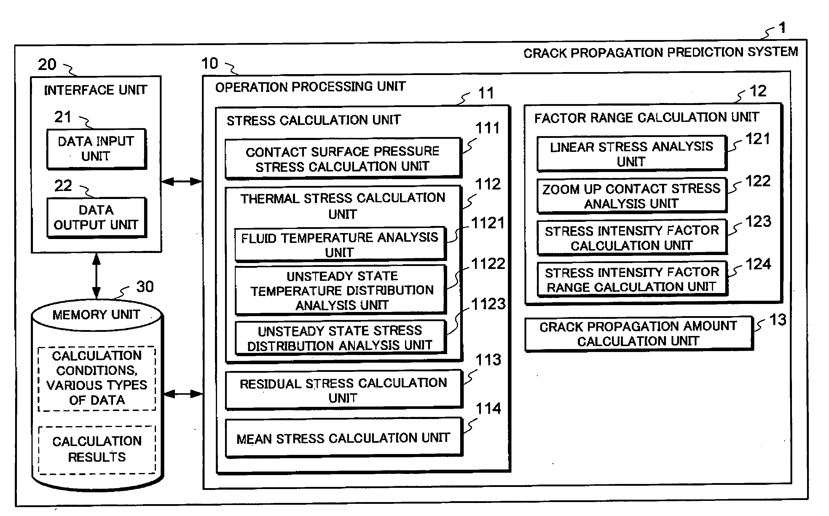
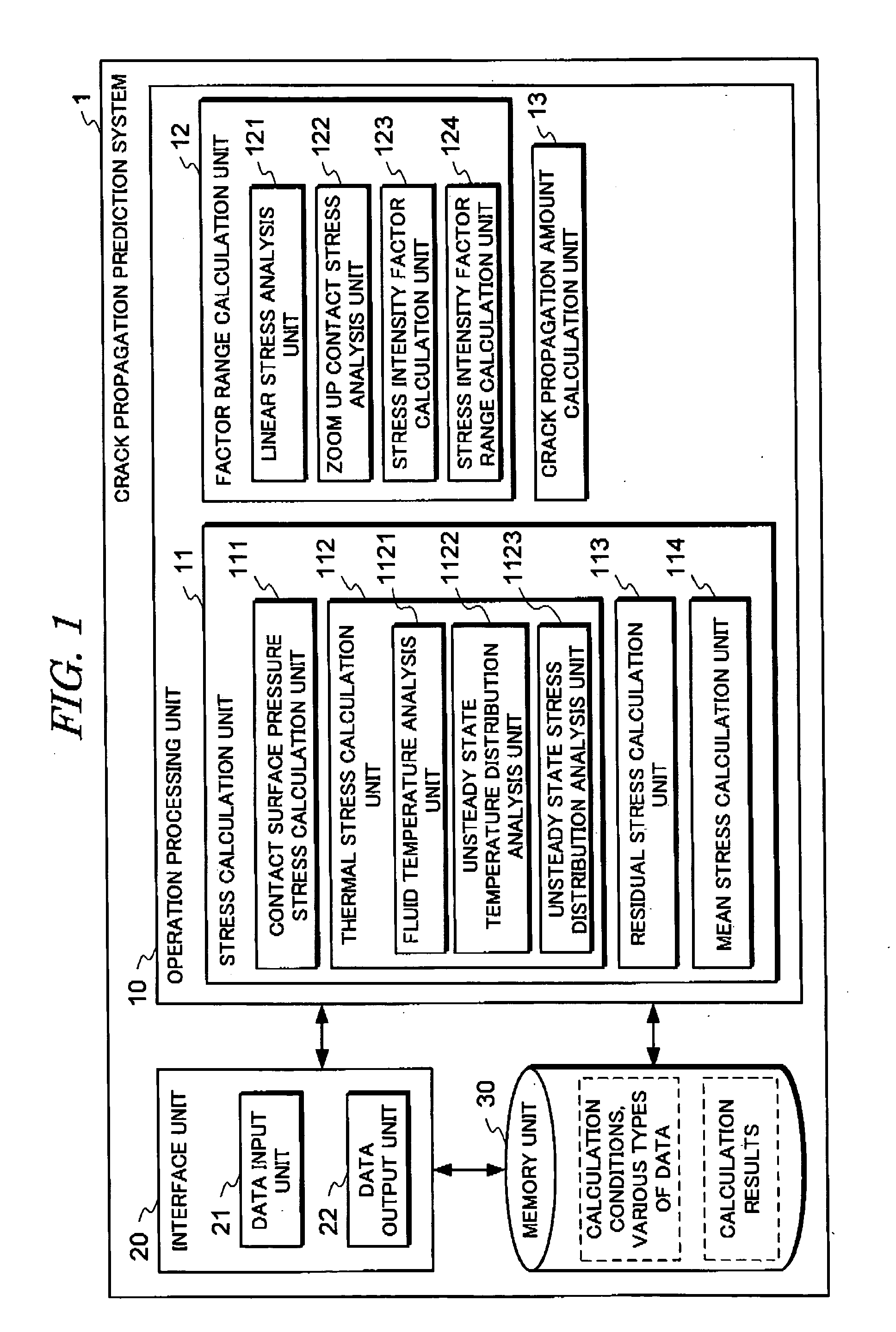
[0035]FIG. 1 is a block diagram showing a generator rotor crack propagation prediction system according to a first embodiment that applies the present invention. As shown in FIG. 1, the crack propagation prediction system 1 includes an operation processing unit 10, an interface unit 20, a memory unit 30, and so on. Each part of the crack propagation prediction system 1 is described in detail below.

[0036] The interface unit 20 includes a data input unit 21, and a data output unit 22. Here, the data input device 21 is an input device such as a mouse or keyboard that inputs signals to a computer in accordance with the operations of the operator. The data output unit 22 is an output device such as a display or a printer that displays or outputs to the operator data input by the data input unit 21 or process results processed within the system.

[0037] The operation processing unit 10 includes a stress calculation unit 11 that calculates the mean stress generated in the s...

second embodiment

[0070] [Configuration]

[0071]FIG. 7 is a block diagram of a generator rotor operating conditions determination support system according to a second embodiment that applies the present invention. The operating conditions determination support system 2 shown in FIG. 7 is a system that determines the operating pattern so that a crack does not extend, in accordance with the size of crack that has been generated in the shaft dovetail. For this purpose, instead of the crack propagation amount calculation unit 13 of the operation processing unit 10 of the crack propagation prediction system 1 according to the first embodiment, an operation limiting value calculation unit 14 and an operation pattern determination unit 15 are provided.

[0072] In the present embodiment, the factor range calculation unit 12 calculates the stress intensity factor range for a crack in the shaft dovetail, based on the size, position, and shape of a crack in the shaft dovetail. The operation limiting value calculat...

third embodiment

[0083] [Configuration]

[0084]FIG. 10 is a block diagram of a generator rotor operation conditions determination support system according to a third embodiment that applies the present invention. When the generator rotor is operated in accordance with an operation pattern so that a crack does not extend, by the same method as the operation conditions determination support system 2 according to the second embodiment, and if it becomes necessary for some reason to exceed the operation limiting value in the operation, the operation conditions determination support system 3 shown in FIG. 10 calculates a new operation limiting value corresponding to the crack propagation and changes the operation pattern accordingly. Therefore, the present embodiment is provided with the operation processing unit 10 of the crack propagation prediction system 1 according to the first embodiment, to which is added a crack size calculation unit 16, and the operation limiting value calculation unit 14 and the ...


PUM


Abstract

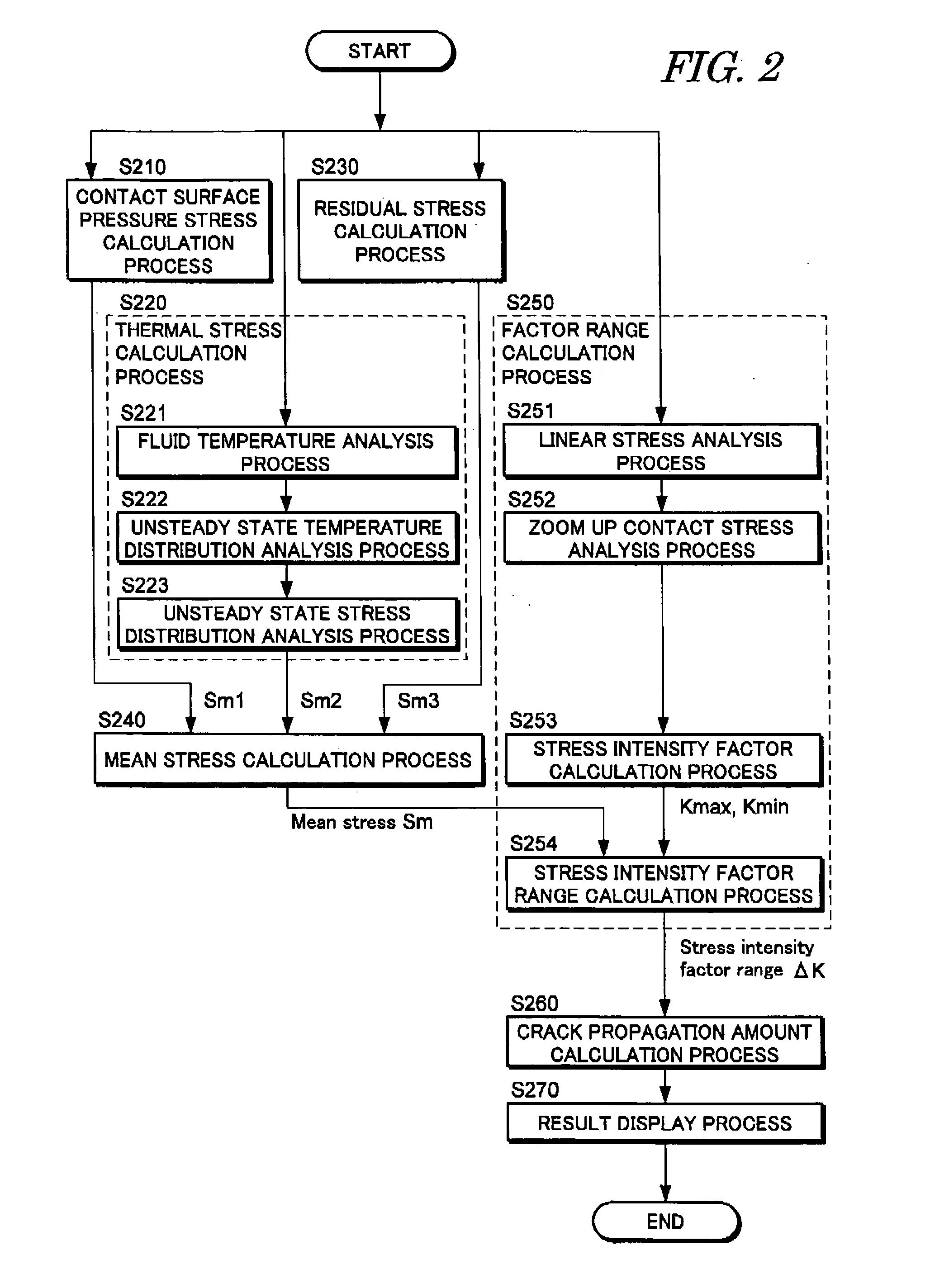
An object of the present invention is to control crack propagation, either by predicting shaft dovetail crack propagation with high accuracy, or by determining operation conditions under which the crack does not extend. The crack propagation prediction system includes an operation processing unit, an interface unit, and a memory unit. The operation processing unit includes a stress calculation unit that calculates the mean stress generated in the shaft dovetail, a factor range calculation unit that calculates the stress intensity factor range for the crack in the shaft dovetail, and a crack propagation amount calculation unit that calculates an amount of the shaft dovetail crack propagation for an arbitrary time period, from the obtained mean stress and the stress intensity factor range, an operation pattern, an operation time, and data on the crack. The stress calculation unit includes as individual calculation units that calculate separately different types of mean stress, a contact surface pressure stress calculation unit, a thermal stress calculation unit, and a residual stress calculation unit, as well as a mean stress calculation unit that sums these mean stresses.

Description

BACKGROUND OF THE INVENTION [0001] 1. Field of the Invention [0002] The present invention relates to technology for predicting crack propagation in the rotors of generators used in energy plant, determining the operation conditions, and controlling operation. [0003] 2. Description of the Related Art [0004] In the rotors of generators used in energy plant, slots are cut in the axial direction, and coils are inserted into the slots. To prevent the coils from being forced out by centrifugal force, dovetails are provided in the outer periphery of the shaft, into which wedges are inserted. [0005] In generator rotors having this type of fitted structure, as a result of centrifugal forces during operation the wedges are forced against the dovetails of the shaft, and at the same time the rotor is subject to repeated bending due to its self-weight. At the ends of the areas of contact between the shaft dovetails and wedges repeated minute relative slippage, or the phenomenon known as fretting...

Claims


Application Information

Patent Timeline
IPC IPC(8): F01D5/30G01M99/00
CPCF01D21/003F05D2260/80G06Q10/04F05D2260/94
Inventor SAITO, KAZUHIROYOSHIOKA, YOMEIMATSUYAMA, KOJIITO, HIROMICHINAGANO, RYOJIKOINUMA, HIROAKI
Owner KK TOSHIBA
Learn More