
Composite structure and method of forming thereof

a composite structure and composite material technology, applied in the field of composite materials, can solve the problems of cracks in the resin, delamination of the plies in adjacent laminated joints, and induction of degradation of laminated joints, so as to and facilitate restricting crack propagation in the resin

Inactive Publication Date: 2018-08-28
THE BOEING CO
View PDF8 Cites 0 Cited by
  • Summary
  • Abstract
  • Description
  • Claims
  • Application Information

AI Technical Summary

Benefits of technology

This patent describes a composite structure that includes multiple components that are joined together to form a joint. There is a gap between the components that is filled with a honeycomb structure containing resin. The honeycomb structure helps to prevent the resin from spreading cracks between the components. This results in a stronger and more reliable joint.

Problems solved by technology

Cracks in the resin may form during manufacture of the composite structures as a result of improper tooling, improper handling of tools, and / or residual tensile strain.
In at least some known composite structures, crack propagation in the radius filler can cause delamination of the plies in adjacent laminated joints.
More specifically, crack propagation in the radius filler may initiate degradation of the laminated joints.
While limiting the formation of cracks in the radius filler would ensure the integrity of the laminated joints, preventing cracks from forming entirely is generally difficult, if not impossible.
Moreover, the difficulty in limiting crack formation in radius fillers increases as composite structures are fabricated in increasingly large sizes.

Method used


Image

  • Composite structure and method of forming thereof
  • Composite structure and method of forming thereof
  • Composite structure and method of forming thereof

Examples


Embodiment Construction

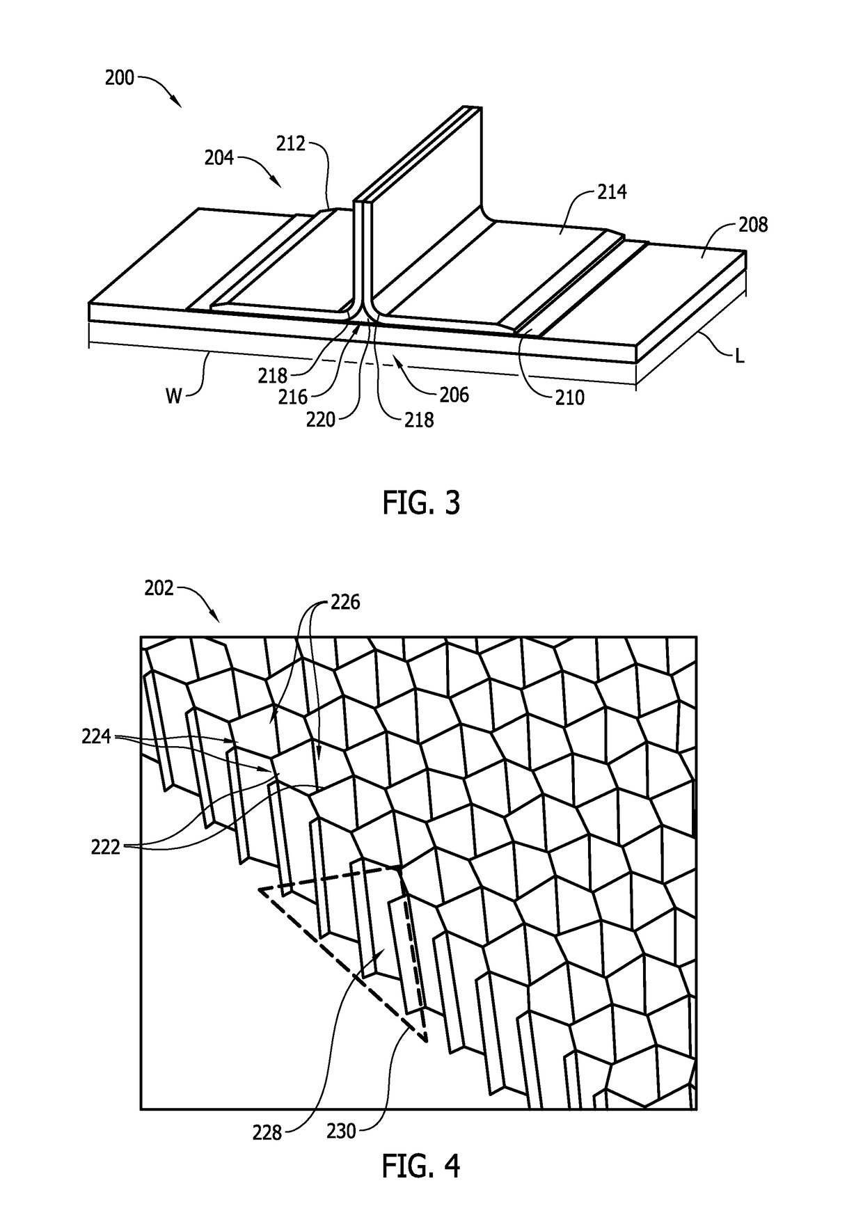
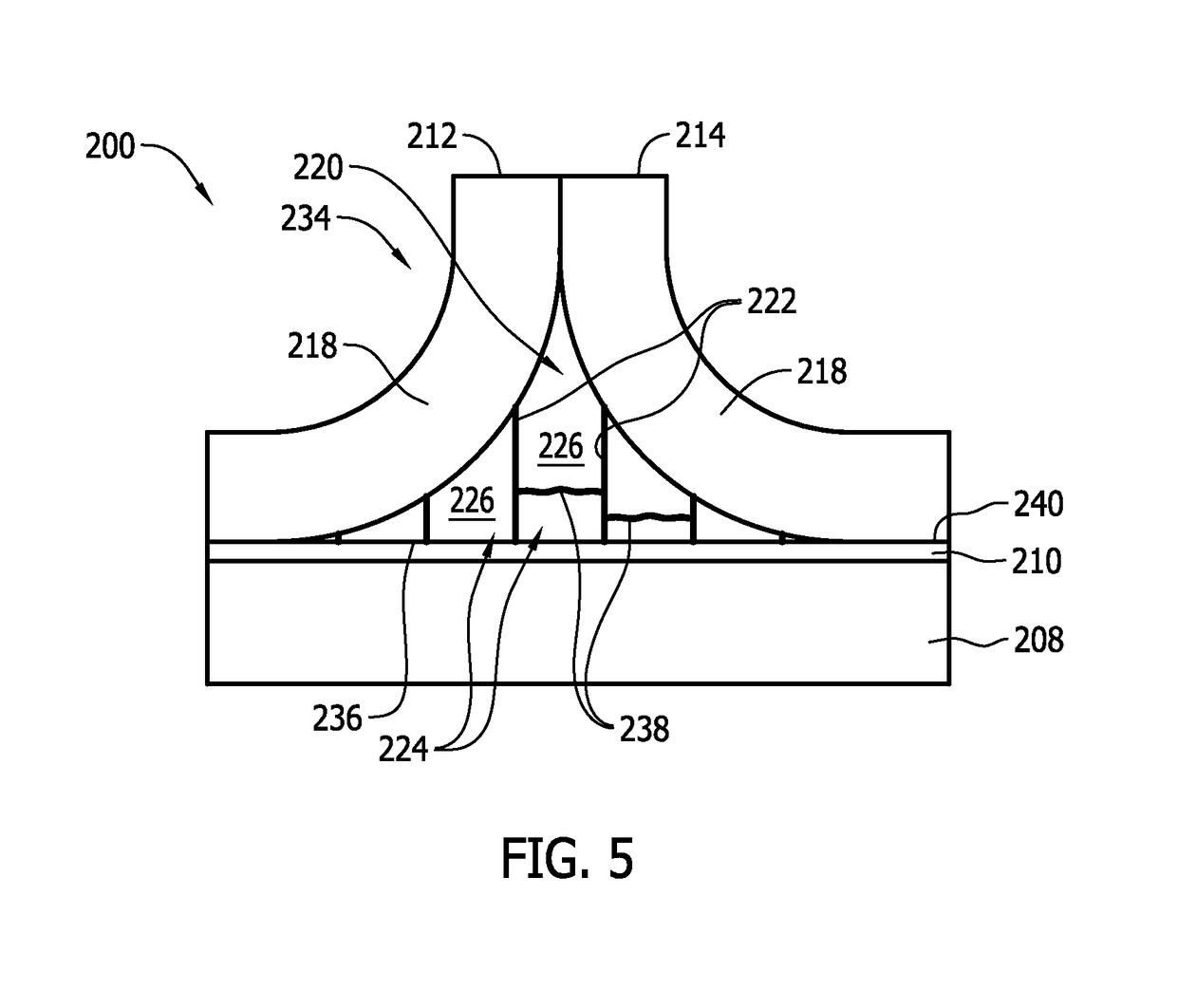
[0014]The implementations described herein relate to composite structures including radius filler structures that facilitate restricting crack propagation of resin in radius gaps (i.e., noodle regions) in the composite structures. In the exemplary implementation, the filler structures include a honeycomb core and an amount of resin within core cells of the honeycomb core. The filler structure is positioned in the radius gap of a composite structure, and as cracks begin to propagate in the resin in the core cells, side walls of the honeycomb core facilitate restricting the crack propagation from spreading between adjacent core cells. As such, the crack propagation is controlled to facilitate maintaining the integrity of a joint defined between adjoining components of the composite structure.

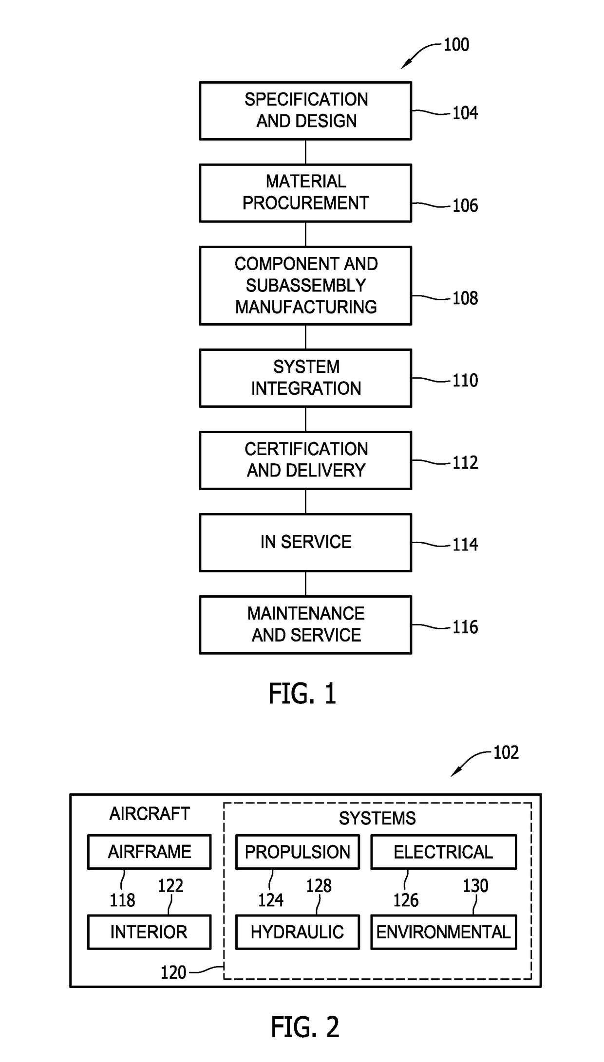
[0015]Referring to the drawings, implementations of the disclosure may be described in the context of an aircraft manufacturing and service method 100 (shown in FIG. 1) and via an aircraft 102 (sh...


PUM

PropertyMeasurementUnit
radiusaaaaaaaaaa
lengthaaaaaaaaaa
shapeaaaaaaaaaa

Abstract

A composite structure that includes a plurality of components coupled together forming a joint, wherein the plurality of components are oriented such that a gap is defined at least partially therebetween. The composite structure also includes a filler structure positioned in the gap. The filler structure includes a honeycomb core including side walls that define a plurality of core cells, and an amount of resin within each of the plurality of core cells. The honeycomb core side walls facilitate restricting crack propagation in the resin from spreading between adjacent pairs of the plurality of core cells.

Description

BACKGROUND[0001]The field of the present disclosure relates generally to composite structures and, more specifically, to filler materials that facilitate restricting crack propagation within noodle regions of composite laminated joints.[0002]Cracking of integrally stiffened composite structures, especially in aerospace applications, often initiates in a radius filler (i.e., noodle) located at an interface between a skin and integral stiffening elements of the composite structures. At least some known radius fillers are formed at least partially from an amount of resin. Cracks in the resin may form during manufacture of the composite structures as a result of improper tooling, improper handling of tools, and / or residual tensile strain. For example, residual tensile strain in composite structures may form as a result of a mismatch between the coefficients of thermal expansion creating a strain environment in the radius filler that exceeds the critical cracking strain of the resin. The...

Claims


Application Information

Patent Timeline
Patent Type & Authority Patents(United States)
IPC IPC(8): B29C70/74B29C70/86B32B3/12B32B3/02B29L31/30
CPCB29C70/745B29C70/865B32B3/12B32B3/02B32B2605/18B29L2031/3076
Inventor CHRISTENSEN, STEPHEN
Owner THE BOEING CO
Learn More