Optical fiber treatment apparatus

Inactive Publication Date: 2007-07-26
HAHNWOOL OPTICS
View PDF5 Cites 13 Cited by
  • Summary
  • Abstract
  • Description
  • Claims
  • Application Information

AI Technical Summary

Benefits of technology

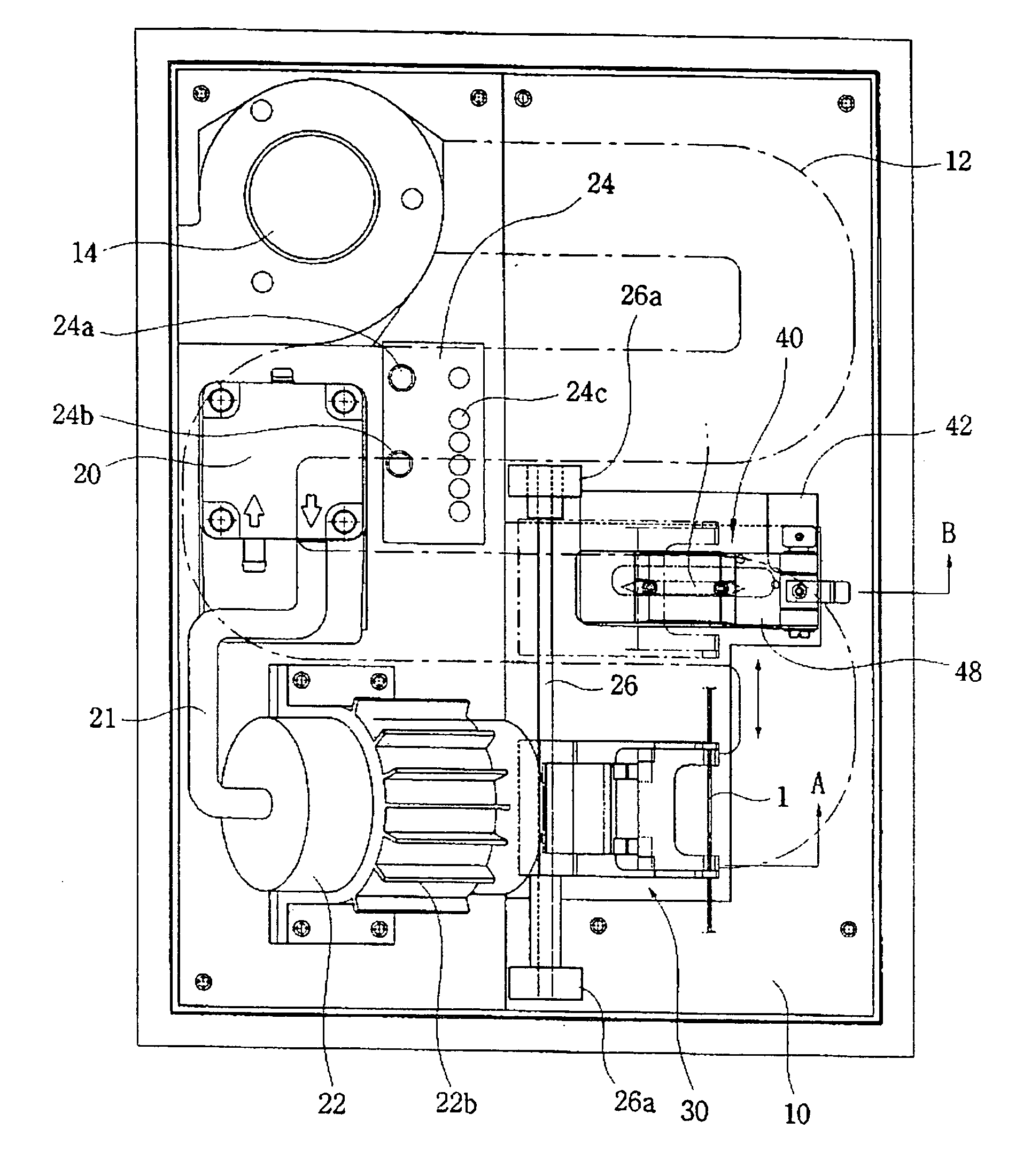
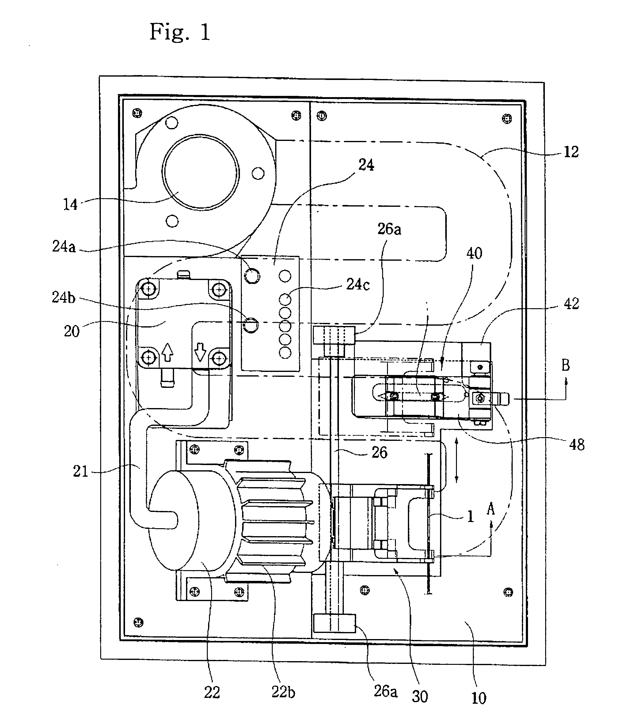
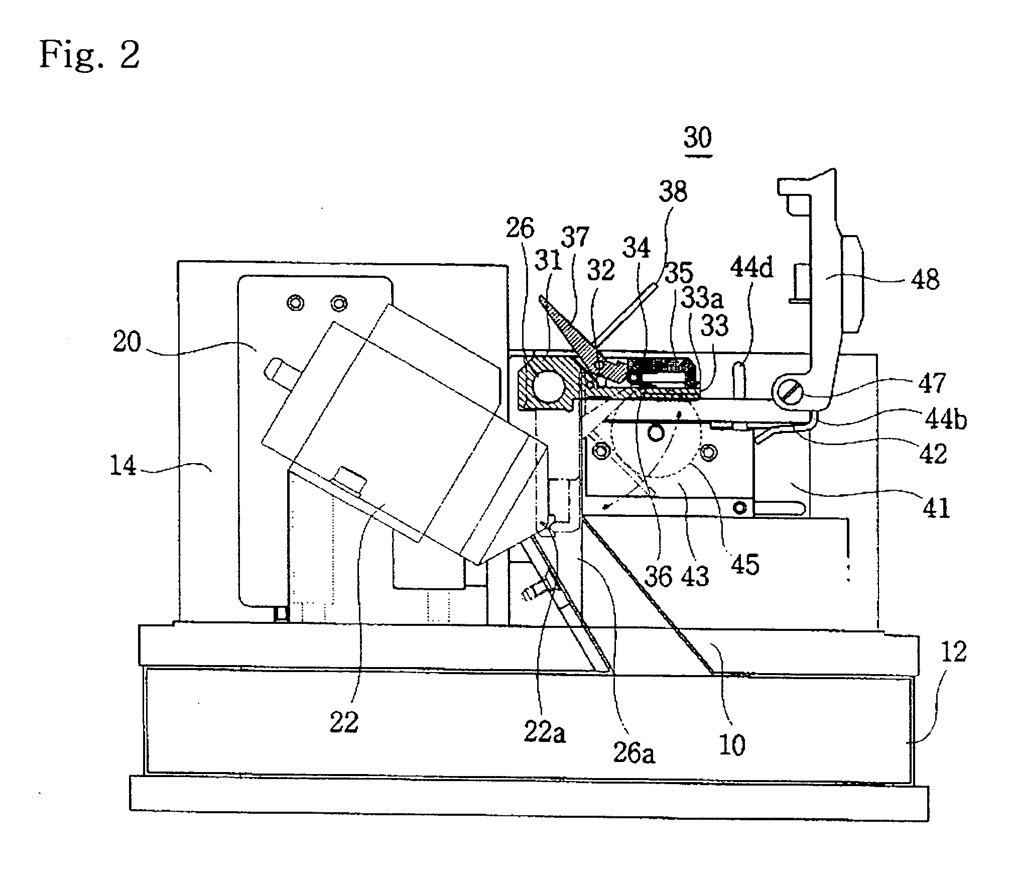
[0022] The cutting means comprises a body having a straight guiding groove perpendicular to the sliding guide and installed on a side of base 10, the side being not faced to the heater and included in a straight section of the clamp means; a slider connected in the straight guiding groove of the body; a slider controlling means provided to both of the body and the slider to control a forward and backward movement of the slider to make it possible to scratch the optical fiber when the clamp means in a cutting position, and to maintain the backward movement of the slider for cutting the optical fiber; a cutter, mounted on the slider having the slider controlling means, for scratching a circumference of the optical fiber along a movement of the slider; a press means operated in the direction of rotating axis on the optical fiber scratched by the cutter to cut the scratched portion of the optical fiber; and a cover rotatably connected to a side of the body and pivoted on the hinge to control the forward and backward movement of the slider, and to control the rise and fall of the press means in connection with the forward and backward movement of the slider.
[0030] The sleeve welding part further comprises a sleeve heater in the heating room to shorten the heating time of the shrinking sleeve. In other example, the sleeve welding part also comprises a heating room with a door for opening / closing the inner space of the room in the base, and a sleeve heater for heating an optical fiber with a shrinking sleeve in the inner space and welding the sleeve.

Problems solved by technology

The contact method would form a fine crack in a surface of optical fiber, in peeling of an outer cover, to produce a serious problem of reliability.
In particular, as the physical property of the outer cover is different from maker to maker, the outer cover would not be removed perfectly, thereby welded to the optical fiber.
However, in these kinds of processes, as each of the processes is performed in an individual apparatus and by manually, the processes are annoying to perform, and consumes lots of times. There is not any problem in case of small product, however, productivity is decreased in case of mass product.

Method used


Image

  • Optical fiber treatment apparatus
  • Optical fiber treatment apparatus
  • Optical fiber treatment apparatus

Examples


further embodiment 1

[0105]FIG. 15 is a cross-sectional view of further embodiment according to the present invention. FIG. 16 is an enlarged front view of important parts in FIG. 15. The figure illustrates the heart in the first and second embodiments in detail

[0106] Referring to figure, a heater 500 in the further embodiment comprises a housing 510, blastpipe 520 and a heating body 530.

[0107] In the housing, a nozzle 512 for discharging air is connected to one end of a hollow body 511 and a closing body 513 for closing the body 511 is connected to the other end of the body. A sharpened point is formed in the tip end of the nozzle 512, and a nozzle opening for discharging air is formed in the sharpened point.

[0108] Further, the closing body 513 is formed with a passing-through hole 514 for passing the heating body 530 from the outside to the inside of the housing 510. An air passage 515 is also formed in the closing body and connected to the blastpipe 520 to supply air from the outside (the air gene...

further embodiment 2

[0116]FIG. 17 is a cross-sectional view of further embodiment 2 according to the present invention. In fig., a sleeve welding part is installed in front of the heater, which is for installing a shrinking sleeve in order to protect a welded point and to weld the shrinking sleeve to the welded point after performing a welding process of optical fibers.

[0117] Referring Fig, a sleeve welding part 600 is structured such that a passage 600 for a heated air from the heater 22 is formed on the base 10 in front of the heater 22, and a heating room is formed in the passage 610.

[0118] The heating room 620 has a door 630 for opening / closing the heating room 620 in order to insert an optical fiber with a shrinking sleeve S in the room. The shrinking sleeve S inserted in the heating room 620 is welded to the optical fiber by a heated air from the heater 22, the heated air also peeling off an outer cover of the optical fiber.

[0119] With such structure, the welding time of the sleeve by the heat...

further embodiment 3

[0122]FIG. 18 is a circuit block diagram of further embodiment according to the present invention. This circuit is more detailed and advanced comparing with the control panel in the foregoing embodiments.

[0123] Referring figure, a control panel 700 according to the further embodiment 3 comprises a key pad 710, a thermistor 720 for sensing temperature, a microprocessor as control part, and a driver 740.

[0124] The key pad 710 is structured to have a key board for turning on / off electronic power and inputting a set-up heating temperature and so forth, and a predetermined button on the base 10. The thermistor 720 is for sensing temperature in a space heated by the heater 22 or the sleeve heater 640 in the further embodiment 2, and installed on a side of the space.

[0125] The microprocessor 730 receives the temperature signal sensed by the thermistor 720 in real time, and controls the heater or the sleeve heater when a difference between the sensed temperature and the set up temperatur...


PUM


Abstract

The present invention relates to an optical fiber treatment apparatus and, more particularly, to an optical fiber treatment apparatus in which an outer cover of an optical fiber is peeled off by hot blast, and processes for peeling off an outer cover of a optical fiber, a cleaning and cutting of the optical fiber, and sleeving can be performed in sequence in order to connect cleaved optical-fibers and to make an optical-fiber device. In order to realize to the present invention, an outer cover peeling-off part is installed on a base, which holds an optical fiber with straight, and discharges a heated air to the straight held optical to remove the outer cover of the optical fiber by using a difference of thermal deformation between the inside outer cover and the outside outer cover. Further, a heater, a clamp means, a cutting means, a sleeve welding part and a control panel are installed on the same base in order to treat the optical fiber is in one apparatus.

Description

BACKGROUND OF THE INVENTION [0001] (1) Field of the Invention [0002] The present invention relates to an optical fiber treatment apparatus and, more particularly, to an optical fiber treatment apparatus in which an outer cover of an optical fiber is peeled off by hot blast, and processes for peeling off an outer cover of a optical fiber, a cleaning and cutting of the optical fiber, and sleeving can be performed in sequence in order to connect cleaved optical-fibers and to make an optical-fiber device. [0003] (2) Description of the Related Arts [0004] An optical fiber is a wave-guide for transmitting light and, in general, used in the form of a bundle of cable. The optical fiber is made of a synthetic resin, and in general, a glass having high transparency. The optical fiber is a double cylinder structure, and has a core and a cladding formed around the core. A synthetic resin encloses the cladding 2 or 3 times. [0005] The optical fiber is very tolerant of electromagnetic interferenc...

Claims


Application Information

Patent Timeline
IPC IPC(8): G02B6/00G02B6/245
CPCG02B6/245
Inventor SONG, JAE
Owner HAHNWOOL OPTICS
Why Eureka
Try Eureka