Temperature control device for fluids
- Summary
- Abstract
- Description
- Claims
- Application Information
AI Technical Summary
Benefits of technology
Problems solved by technology
Method used
Image

Examples
first embodiment
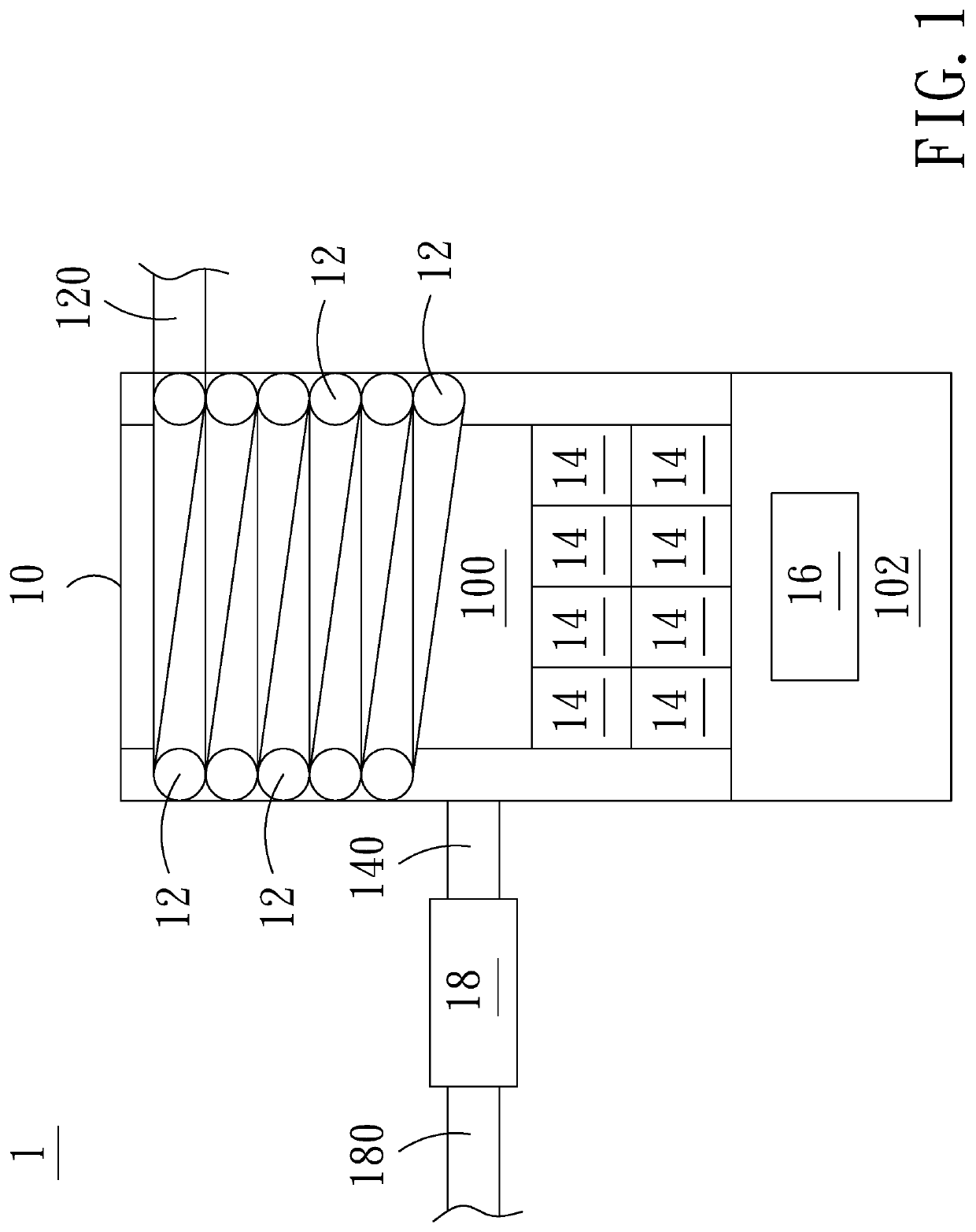
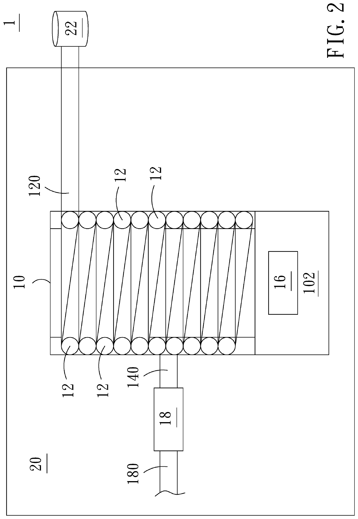
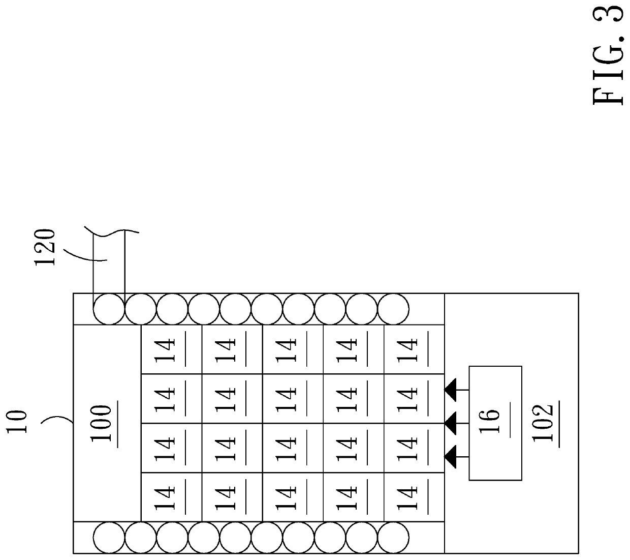
[0031]Please refer to FIG. 1, which shows a first structural schematic diagram of the temperature control device for fluids according the present application. As shown in the figure, the temperature control device 1 for fluids according to the present application comprises: a furnace 10, including a first accommodating space 100 and a second accommodating space 102, the first accommodating space 100 disposed on one side of the furnace 10, and the second accommodating space 102 disposed on the other side of the furnace 10; a fluid pipe 12, surrounding the outside of the first accommodating space 100; a plurality of regenerative members 14, disposed in the first accommodating space 100; a burner 16, disposed in the second accommodating space 102; and an air control device 18, disposed on one side of the furnace 10; where the burner 16 heats the first accommodating space 100 to store heat in the plurality of regenerative members 14 and conduct the thermal energy to the fluid pipe 12 fo...
third embodiment
[0044]Please refer to FIG. 7 and FIG. 8, which show a first and a second structural schematic diagram of the temperature control device for fluids according the present application. As shown in the figures, the temperature control device 1 for fluids according to the present application comprises: a furnace 10, including a first accommodating space 100, a second accommodating space 102, and an opening 104, the first accommodating space 100 disposed on one side of the furnace 10, the second accommodating space 102 disposed on the other side of the furnace 10, and the opening 104 disposed between and communicating with the first accommodating space 100 and the second accommodating space 102; a fluid pipe 12, surrounding the outside of the first accommodating space 100; a regenerative member 14′, disposed in the first accommodating space 100, and including a breach 142′ corresponding to the opening 104; a burner 16, disposed in the second accommodating space 102; and an air control dev...
fourth embodiment
[0047]According to the present application, the air control device 18 does not communicate with the first accommodating space 100 of the furnace 18 and the fluid pipe 12 does not communicate with the water storage tank 22. Instead, the furnace 10 communicates with the thermal processor 28. The fluid pipe 12 transports the heated liquid 12 to the thermal processor 28. The heated air 140 is also transported to the thermal processor 28 via related pipes (not shown in the figure). The thermal processor 28 processes the heated liquid 120 and the heated air 140 such that the heated air 140 transported to the air control device 18 via the first pipe 280 is maintained at an appropriate temperature, and the heated liquid 120 transported to water storage tank 22 via the second pipe 282 is maintained at an appropriate temperature. To elaborate, the heated liquid 120 transported to the thermal processor 28 is moved by the related pipes of the thermal processor 28. By using the thermal conductio...
PUM
 Abstract
Description
Claims
Application Information
 - R&D
- Intellectual Property
- Life Sciences
- Materials
- Tech Scout
- Unparalleled Data Quality
- Higher Quality Content
- 60% Fewer Hallucinations
Browse by: Latest US Patents, China's latest patents, Technical Efficacy Thesaurus, Application Domain, Technology Topic, Popular Technical Reports.
© 2025 PatSnap. All rights reserved.Legal|Privacy policy|Modern Slavery Act Transparency Statement|Sitemap|About US| Contact US: help@patsnap.com