Image forming apparatus
a technology of image forming apparatus and forming head, which is applied in the direction of image enhancement, digital output to print units, instruments, etc., can solve the problems of difficult continuous and smooth change of energy distribution in scanning direction, prone to discontinuous points of energy distribution, and difficult to manufacture recording devices whose characteristics coincide accurately. , to achieve the effect of good output imag
- Summary
- Abstract
- Description
- Claims
- Application Information
AI Technical Summary
Benefits of technology
Problems solved by technology
Method used
Image
Examples
embodiment 1
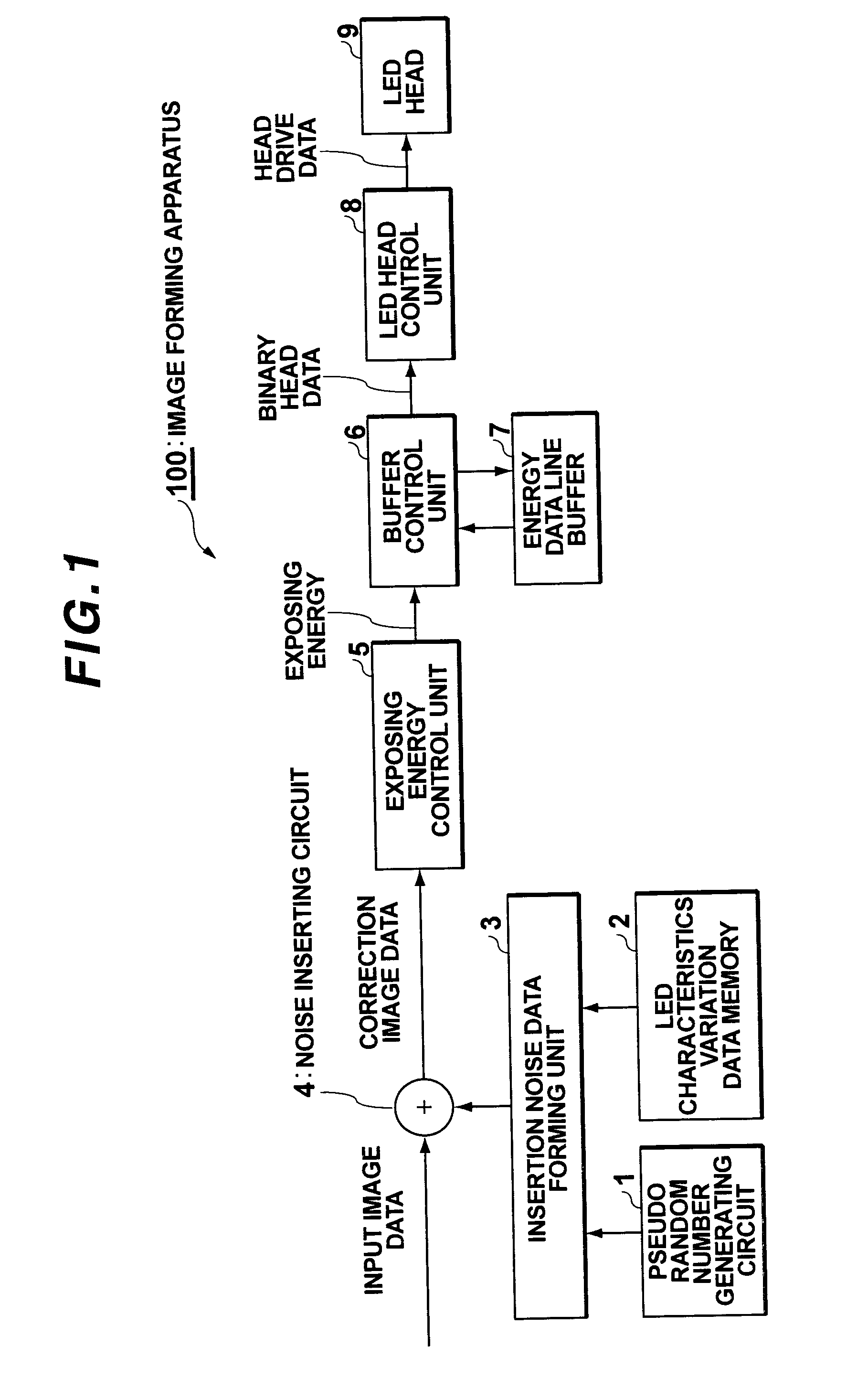
[0039]FIG. 1 is a block diagram of a construction of an image forming apparatus according to an embodiment 1.
[0040] As shown in the diagram, an image forming apparatus 100 according to the embodiment 1 has: a pseudo random number generating circuit 1; an LED characteristics variation data memory 2;
[0041] an insertion noise data forming unit 3; a noise inserting circuit 4; an exposing energy control unit 5; a buffer control unit 6; an energy data line buffer 7; an LED head control unit 8; and an LED head 9.
[0042] The pseudo random number generating circuit 1 is a circuit to form noises which are inserted into input image data which is transmitted from an upper apparatus (not shown).
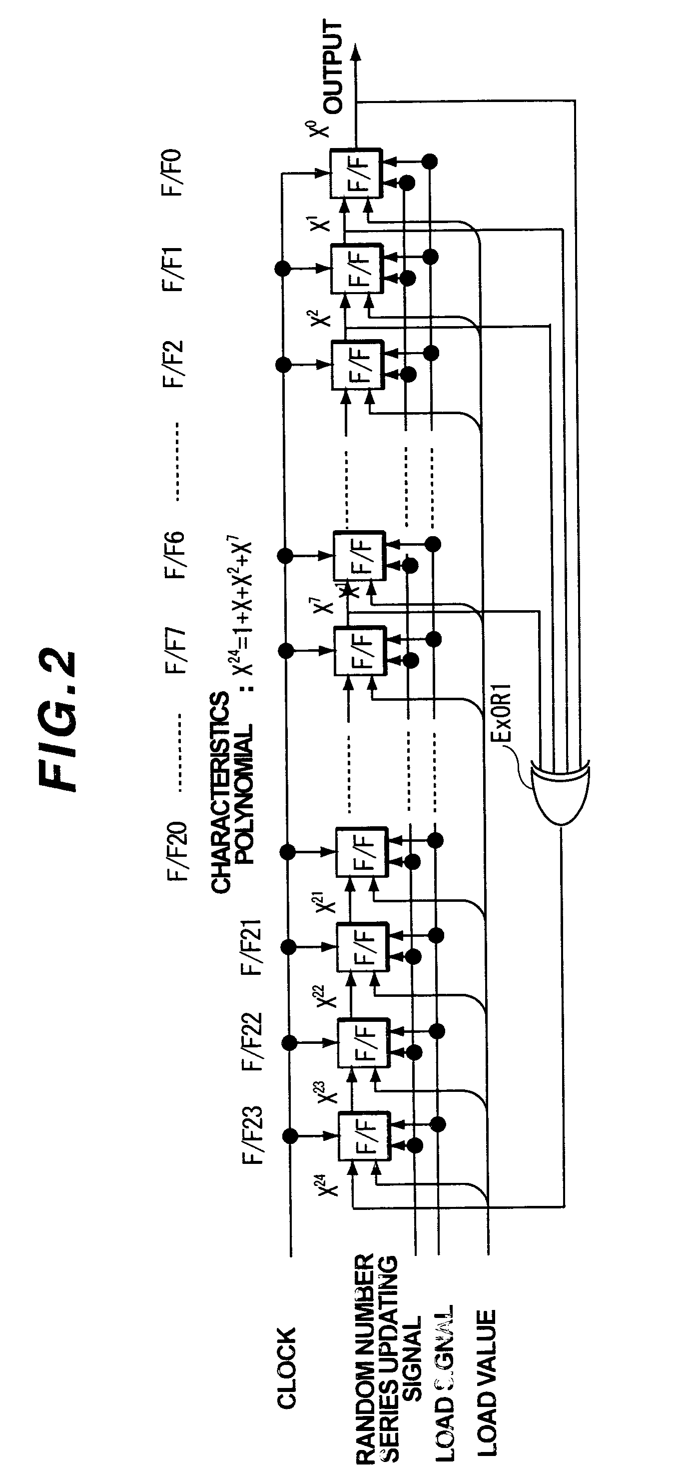
[0043]FIG. 2 is a constructional diagram of the pseudo random number generating circuit in the embodiment 1.
[0044] As shown in the diagram, the pseudo random number generating circuit 1 in the embodiment is an M series pseudo random number generating circuit comprising: 24 shift registers F / F0 to F / F2...
embodiment 2
[0086]FIG. 12 is a block diagram of a construction of an image forming apparatus according to an embodiment 2.
[0087] As shown in the diagram, an image forming apparatus 200 according to the embodiment 2 has: the pseudo random number generating circuit 1; the LED characteristics variation data memory 2; an insertion noise data forming unit 21; the noise inserting circuit 4; the exposing energy control unit 5; the buffer control unit 6; the energy data line buffer 7; the LED head control unit 8; and the LED head 9. Only portions different from those in the embodiment 1 will be described hereinbelow. Portions similar to those in the embodiment 1 are designated by the same reference numerals or characters and their explanation is omitted.
[0088] The insertion noise data forming unit 21 is a portion for receiving the output of the pseudo random number generating circuit 1, reading out the correction values from the LED characteristics variation data memory 2, and forming the insertion n...
embodiment 3
[0098]FIG. 15 is a block diagram of a construction of an image forming apparatus according to an embodiment 3.
[0099] As shown in the diagram, an image forming apparatus 300 according to the embodiment 3 has: a pseudo random number generating circuit 32; the LED characteristics variation data memory 2; the insertion noise data forming unit 21; the noise inserting circuit 4; the exposing energy control unit 5; the buffer control unit 6; the energy data line buffer 7; the LED head control unit 8; and the LED head 9. Only portions different from those in the embodiment 1 or 2 will be described hereinbelow. Portions similar to those in the embodiment 1 or 2 are designated by the same reference numerals or characters and their explanation is omitted.
[0100] The pseudo random number generating circuit 32 is a circuit for forming noises which are inserted into the input image data which is transmitted from the upper apparatus (not shown).
[0101]FIG. 16 is a constructional diagram of the ps...
PUM
 Abstract
Description
Claims
Application Information
 - R&D
- Intellectual Property
- Life Sciences
- Materials
- Tech Scout
- Unparalleled Data Quality
- Higher Quality Content
- 60% Fewer Hallucinations
Browse by: Latest US Patents, China's latest patents, Technical Efficacy Thesaurus, Application Domain, Technology Topic, Popular Technical Reports.
© 2025 PatSnap. All rights reserved.Legal|Privacy policy|Modern Slavery Act Transparency Statement|Sitemap|About US| Contact US: help@patsnap.com


