
Method and apparatus for determining gas content of subsurface fluids for oil and gas exploration

a technology of subsurface fluids and gas content, which is applied in the direction of survey, instruments, and well accessories, can solve the problems of non-economic petroleum residue within macro or microporosity in reservoir sections, inability to distinguish between wet gas, condensate and oil with current gc based instruments, and inability to accurately determine the gas content of subsurface fluids

Inactive Publication Date: 2007-07-26
SCHLUMBERGER TECH CORP
View PDF5 Cites 34 Cited by
  • Summary
  • Abstract
  • Description
  • Claims
  • Application Information

AI Technical Summary

Benefits of technology

Enables accurate, real-time characterization of petroleum fluids, improving drilling and completion decisions by providing detailed information on petroleum distribution, quality, and past fluid presence, reducing the risk of missing productive horizons and enhancing exploration efficiency.

Problems solved by technology

Leakage or remigration of petroleum-bearing reservoirs can result in retained, non-economic petroleum residue within macro or microporosity in the reservoir sections.
Current methods provide a very incomplete record of above-described subterranean fluid history recorded by borehole and cuttings volatiles, due to the industry-standard choice of instrumentation and methodology.
While it is true that dry gas can be distinguished from wet gas or oil with well site gas detection equipment, it is difficult to distinguish between wet gas, condensate and oil with current GC based instrumentation.
Ratios of low molecular weight paraffins are used in attempts to distinguish oil from gas (e.g., wetness factors), but these are often inadequate for the task.
It is not possible with GC-based methods to distinguish compounds that exist as a free phase in the pore system from those that may be dissolved in an aqueous pore fluid since GC methods generally do not measure a wide range of carbon species.
This limitation prevents, for instance, distinguishing petroliferous formations from underlying water legs or water-bearing formations that are charged up dip, based on concentrations of water-soluble compounds such as benzene and acetic acid.
Current art teaches away from using mass spectrometry (MS) on wellsite because of a perceived lack of reliability due to rugged conditions encountered in the field.
Third, multiple scans, and specifically a large number of scans are advocated by prior art, however, it has been learned that the advocated procedure of jump scanning coupled with fast scan rates to get an abundance of scans in the time frame required, produces poor mass resolution due to recovery limitations of the electronics and decreases overall sensitivity because of poor counting statistics.
This procedure has several disadvantages, including potential cross contamination of samples and / or volatiles, development of progressively higher backgrounds during analysis of large sample sets unless unrealistically long pump-down times are employed between each sample, and selective near-instantaneous adsorption of released volatiles onto the surfaces of all samples in the chamber, resulting in fractionated and muted responses.
Additionally, trace residual natural organic compounds, if present on grain surfaces, are additively contributed to the background and can create a disproportionately high background, which affects the baseline sensitivity of the analysis.
While attempts have been made to improve some aspects of well site hydrocarbon detection (e.g., Quantitative Fluorescence Technique (QFT), Quantitative Gas Analysis (QGA), membrane technology), there is currently no comprehensive apparatus for analyzing past and present pore fluids in the necessary detail.
Cuttings volatile analysis can be completed on archived samples, but the surface adsorbed portion of the signal, discussed above, as well as the real-time application to drilling and completion operations are lost.

Method used


Image

  • Method and apparatus for determining gas content of subsurface fluids for oil and gas exploration
  • Method and apparatus for determining gas content of subsurface fluids for oil and gas exploration
  • Method and apparatus for determining gas content of subsurface fluids for oil and gas exploration

Examples


Embodiment Construction

[0047] The embodiments discussed herein are merely illustrative of specific manners in which to make and use the invention and are not to be interpreted as limiting the scope of the instant invention.

[0048] While the invention has been described with a certain degree of particularity, it is to be noted that many modifications may be made in the details of the invention's construction and the arrangement of its components without departing from the spirit and scope of this disclosure. It is understood that the invention is not limited to the embodiments set forth herein for purposes of exemplification.

[0049] It is desirable to have a record of mass to charge ratio (MCR) for a borehole volatiles and / or cuttings volatiles sample that reliably permits comparison of compounds represented by one or more MCR to one or more others.

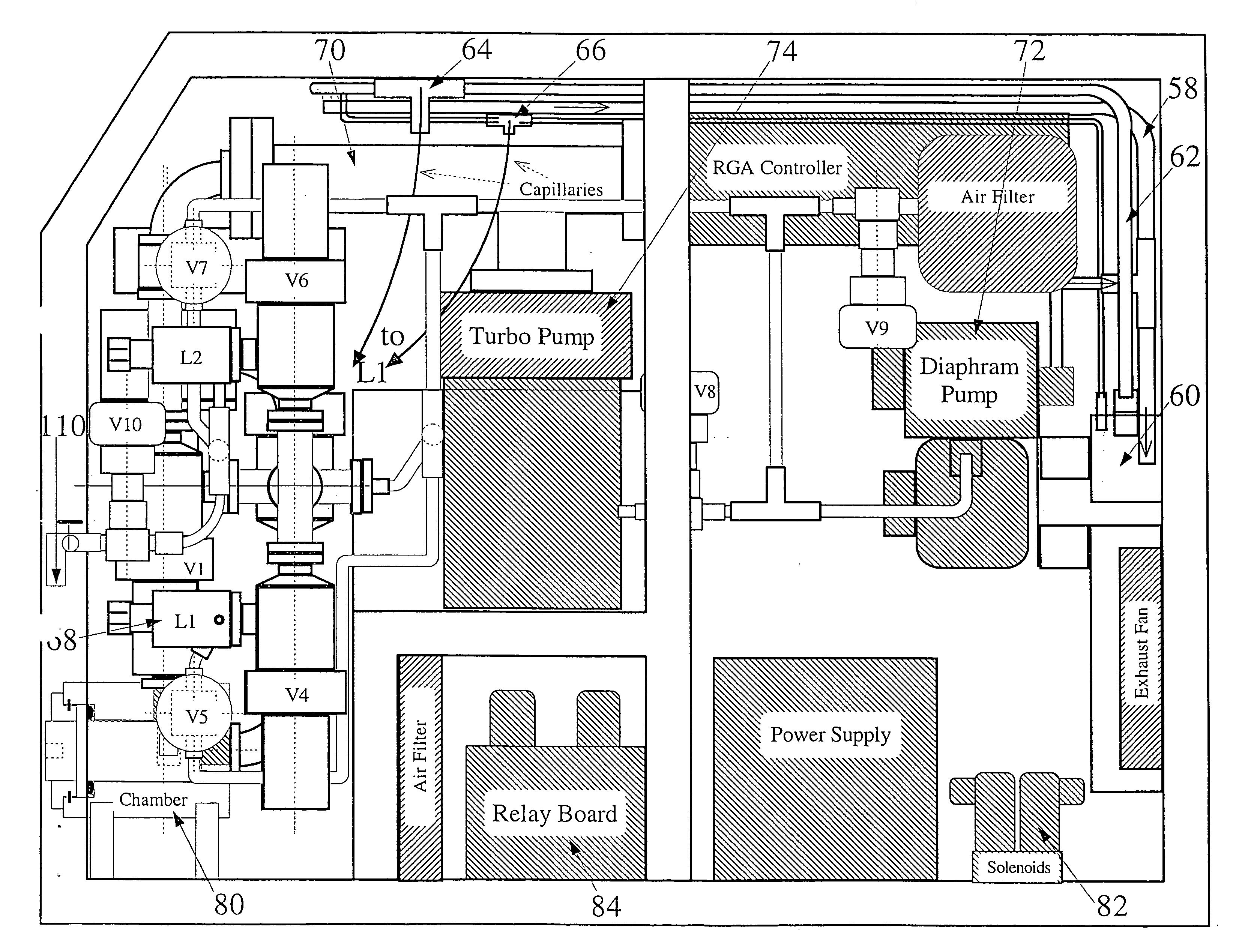
[0050] According to one aspect of the invention, there is provided a mass spectrometry (MS) system for producing such a reliable record. The MS system is confi...


PUM


Abstract

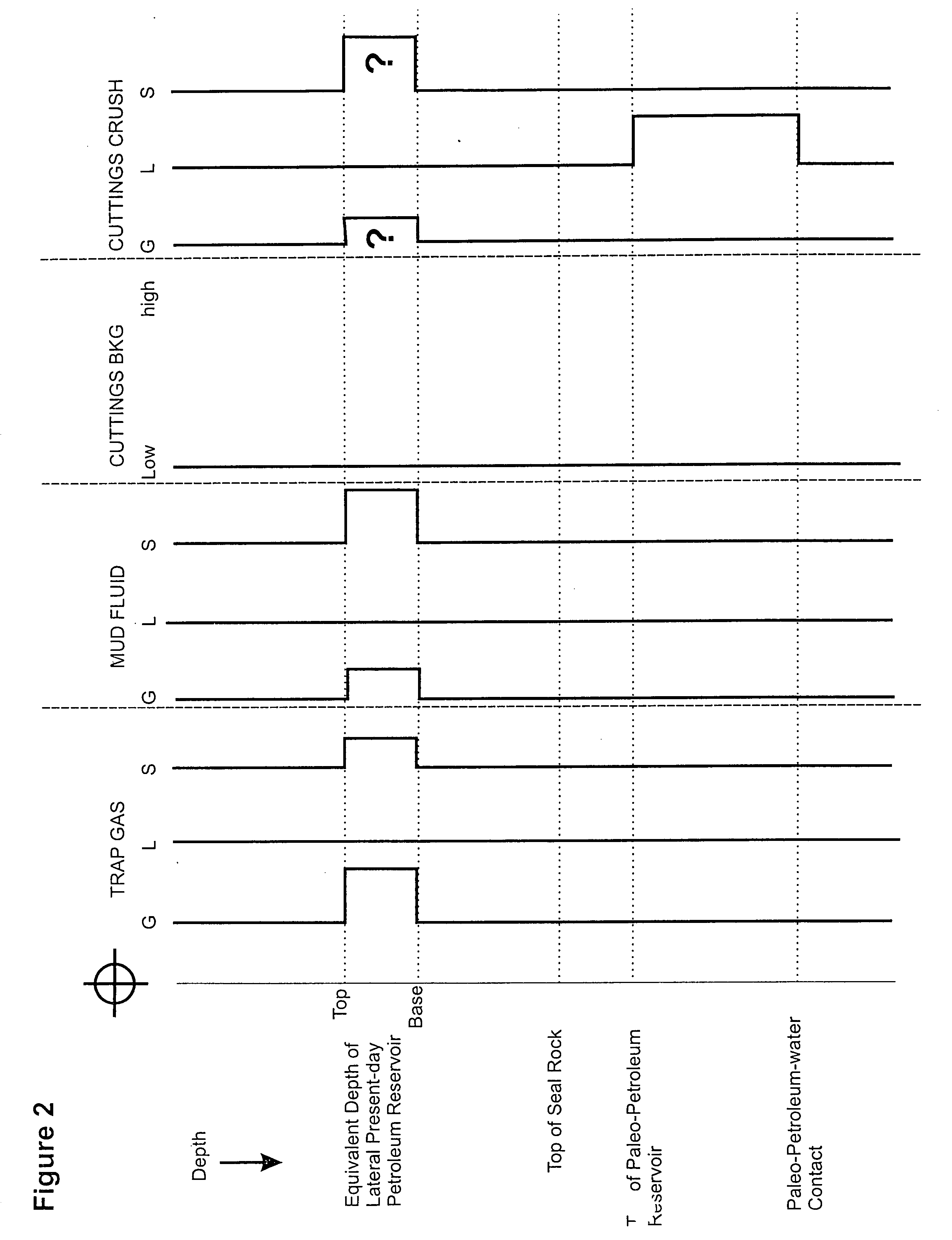
A process to analyze fluid entrained in well boreholes. The process includes gathering trap gas samples from return of drilling mud at multiple depths. The process also includes the steps of subjecting the samples to mass spectrometry in order to determine mass to charge ratios data of hydrocarbons and analyzing the mass to charge ratios data in relation to depth or time. Samples from at least one other source may also be gathered and analyzed chosen from the group consisting of mud fluid analysis, cuttings backgrounds analysis and cuttings crush analysis.

Description

CROSS REFERENCE TO RELATED APPLICATIONS [0001] This application is based on U.S. Provisional Patent Application No. 60 / 295,452 filed Jun. 2, 2001 entitled “Method and Apparatus For Determining The Gas Content of Present and Past Subsurface Fluids For Oil and Gas Exploration”. BACKGROUND OF THE INVENTION [0002] 1. Field of the Invention. [0003] The present invention relates to an apparatus and method for real-time analysis of 1) trap gas, 2) mud fluid and / or 3) cuttings for gas content in conjunction with exploring the earth's subsurface for economic, producible hydrocarbons. In another aspect, the present invention relates to mapping the distribution, chemistry and relative and / or absolute abundance of chemical species analyzed by the above apparatus and method. [0004] 2. Prior Art. [0005] Petroleum resources are the cumulative result of generation, expulsion, migration and trapping of petroleum in sedimentary basins. Petroleum fluids (both gas and liquid) are retained in the source...

Claims


Application Information

Patent Timeline
Patent Type & Authority Applications(United States)
IPC IPC(8): E21B49/08E21B47/00H01J49/26
CPCE21B49/08E21B21/01H01J49/26
Inventor STERNER, STEVEN MICHAELHALL, DONALD LEWISSHENTWU, WELLS
Owner SCHLUMBERGER TECH CORP
Learn More