
Vehicle surroundings monitoring apparatus, method, and program

a technology for monitoring apparatus and surroundings, applied in image analysis, image enhancement, instruments, etc., can solve problems such as difficulty in separating detection objects from background objects, and achieve the effects of improving the extraction accuracy of objects, low overlap possibility, and accurate detection

Inactive Publication Date: 2007-07-19
HONDA MOTOR CO LTD
View PDF63 Cites 94 Cited by
  • Summary
  • Abstract
  • Description
  • Claims
  • Application Information

AI Technical Summary

Benefits of technology

The present invention provides a vehicle surroundings monitoring apparatus and method that can accurately detect objects around the vehicle from images obtained by multiple image sensors. The apparatus includes an object extraction process unit that extracts objects from a predetermined standard image based on the driving environment detected by the driving environment detection process unit. The standard image is selected based on the driving environment to reduce the possibility of overlap between the detection object and background objects. Additionally, the apparatus includes a position detection process unit that detects the position of each object in relation to the vehicle based on the images obtained by the image sensors. This improves the accuracy of object detection and positioning.

Problems solved by technology

If the detection object overlaps the background object in the image, it is difficult to separate the detection object from the background object in the image after extracting the objects from the image.

Method used


Image

  • Vehicle surroundings monitoring apparatus, method, and program
  • Vehicle surroundings monitoring apparatus, method, and program
  • Vehicle surroundings monitoring apparatus, method, and program

Examples


first embodiment

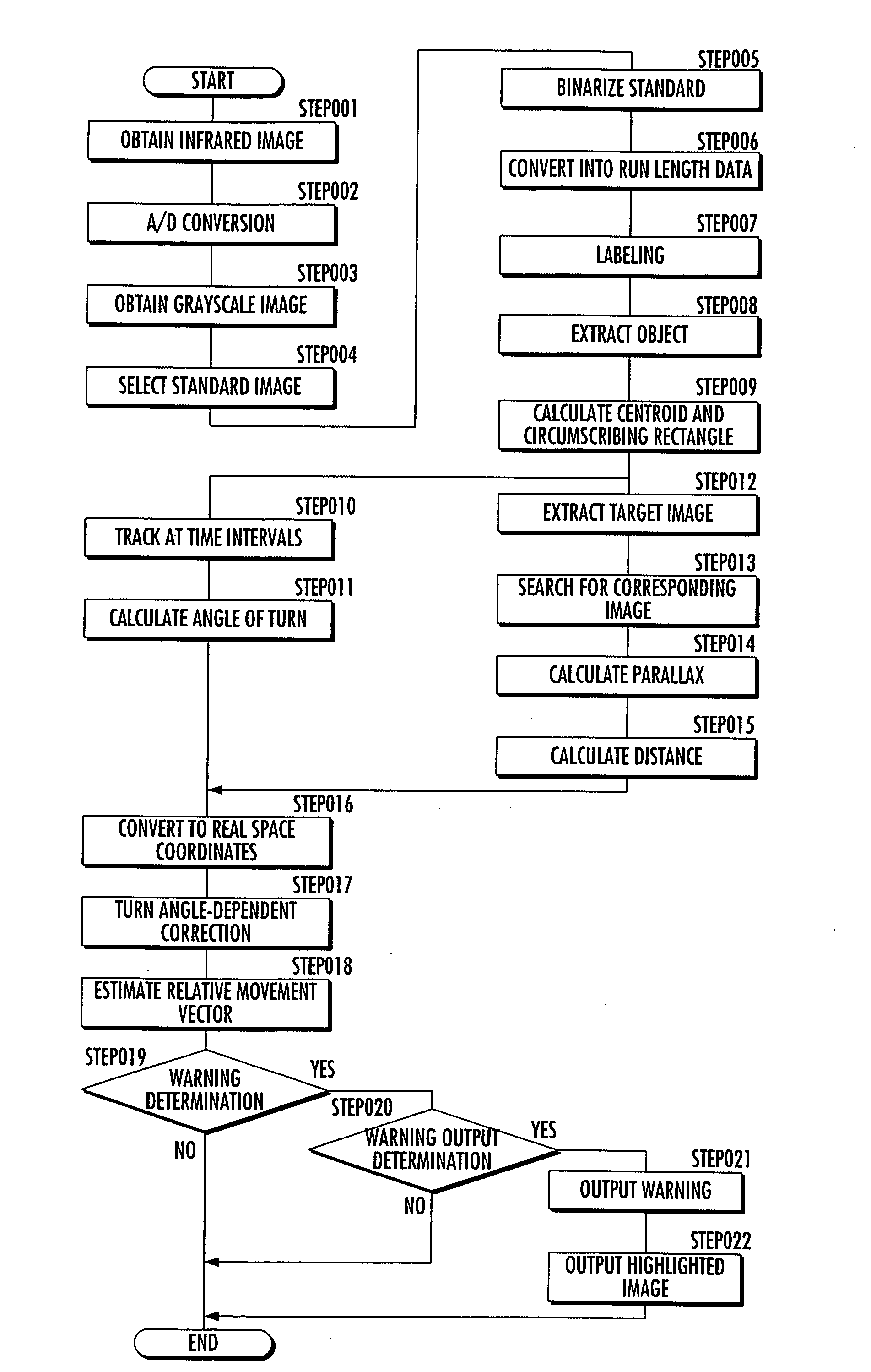
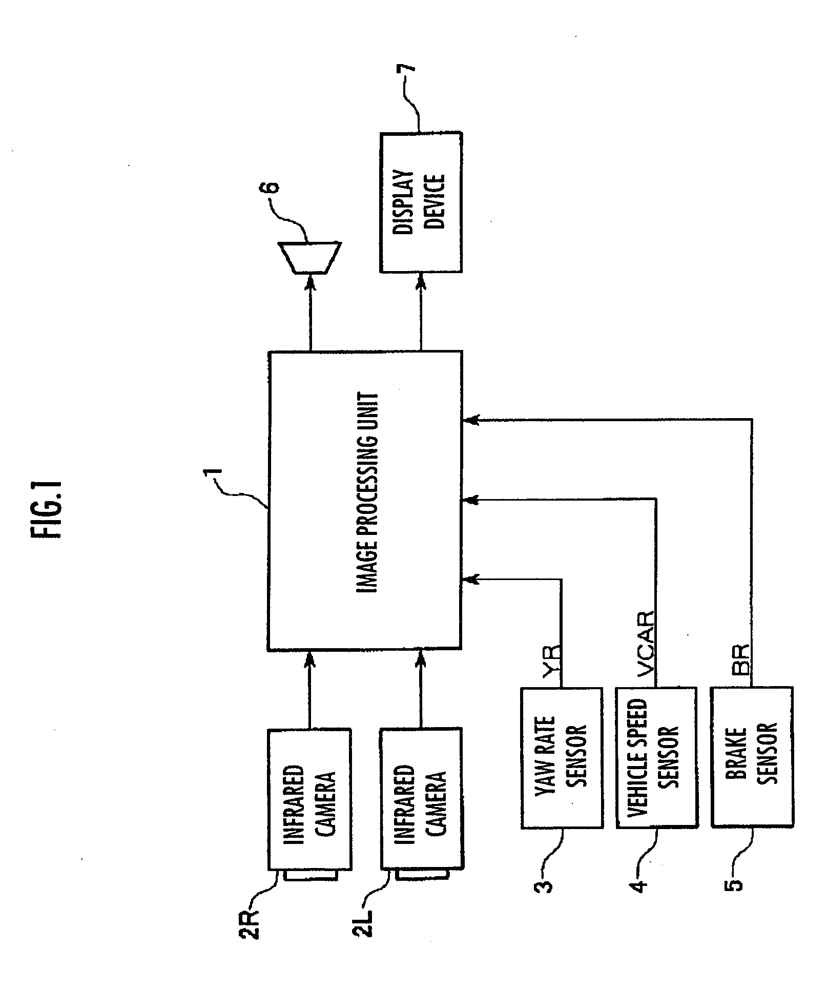
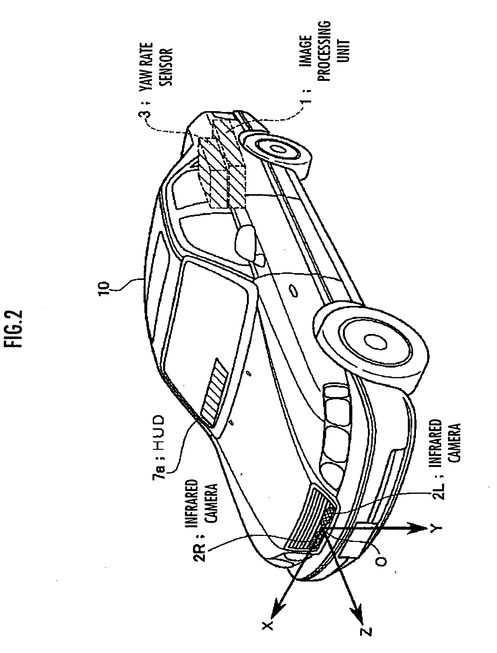
[0060]A first embodiment of the present invention will be described, first, with reference to FIG. 1 to FIG. 11. It should be noted that this embodiment corresponds to a vehicle surroundings monitoring apparatus according to the first aspect of the present invention.

[0061]Referring to FIG. 1 and FIG. 2, the vehicle surroundings monitoring apparatus according to this embodiment includes an image processing unit 1, which is an electronic unit having a central processing unit (CPU) which controls the vehicle surroundings monitoring apparatus. The image processing unit 1 is connected to the following mounted on the vehicle 10: two infrared cameras 2R and 2L, a yaw rate sensor 3 which detects a yaw rate of the vehicle 10, a vehicle speed sensor 4 which detects a traveling speed (vehicle speed) of the vehicle 10, and a brake sensor 5 which detects brake operations of the vehicle 10.

[0062]Furthermore, the image processing unit 1 is connected to a loudspeaker 6 which generates a voice alarm...

second embodiment

[0117]The following describes a second embodiment of the present invention. This embodiment is the same as the first embodiment except that the vehicle 10 is provided with a navigation system, instead of the input device. In the description below, the same reference numerals designate the same components as in the first embodiment and their description is omitted here.

[0118]In this embodiment, the image processing unit 1 is connected to the navigation system mounted on the vehicle 10. The driving environment detection process unit as a function of the image processing unit 1 detects a roadside of a road where the vehicle 10 exists as a driving environment based on information on the roadside of the road obtained by the navigation system. The information on the roadside of the road obtained by the navigation system is information such that, for example, the traffic pattern on the road where the vehicle 10 exists is a left-hand pattern. Similarly to the first embodiment, it is assumed...

third embodiment

[0122]The following describes a third embodiment of the present invention. This embodiment is the same as the first embodiment except that the image processing unit 1 includes a relative speed calculation process unit as its function, instead of the input device. In the description below, the same reference numerals designate the same components as in the first embodiment and their description is omitted here.

[0123]In the vehicle surroundings monitoring apparatus according to this embodiment, the image processing unit 1 includes, as a function thereof, the relative speed calculation process unit which calculates the relative speed of an object extracted by the object extraction process unit with respect to the vehicle 10. The relative speed calculation process unit calculates the relative speed of the extracted object with respect to the vehicle 10, for example, by using the position of the object extracted by the object extraction process unit, which has been detected by the positi...


PUM


Abstract

A vehicle surroundings monitoring apparatus, method, and program capable of reducing a possibility of overlap between a detection object and a background object in a standard image when detecting objects around the vehicle from images obtained by a plurality of image sensors so as to detect the objects accurately. The vehicle surroundings monitoring apparatus detects the objects existing around the vehicle (10) from the images obtained by the image sensors (2R, 2L) mounted on the vehicle (10). The vehicle surroundings monitoring apparatus includes an object extraction process unit (1) which performs a process of extracting the objects for a predetermined standard image of the images obtained by the image sensors (2R, 2L), a driving environment detection process unit (1) which detects a driving environment of the vehicle (10), and a standard image selection process unit (1) which selects the standard image for use in the process of the object extraction process unit (1) anew according to the detected driving environment.

Description

BACKGROUND OF THE INVENTION[0001]1. Field of the Invention[0002]The present invention relates to a vehicle surroundings monitoring apparatus and method which detects an object existing in the surroundings of a vehicle from images obtained by a plurality of image sensors such as cameras mounted on the vehicle, and more particularly to a program for use in causing a computer to perform processing of the apparatus.[0003]2. Description of the Related Art[0004]In recent years, there is known a technology of imaging the surroundings of a vehicle with a plurality of image sensors such as CCD cameras mounted on the vehicle, detecting a distance between an object such as a pedestrian existing around the vehicle and the vehicle based on a difference (parallax) between images obtained by a plurality of image sensors, determining an object such as a pedestrian at high risk of collision on the basis of the detected result, and presenting information to a driver (for example, refer to Japanese Pa...

Claims


Application Information

Patent Timeline
Patent Type & Authority Applications(United States)
IPC IPC(8): G06K9/00G06V10/28
CPCB60W40/04G06K9/38G06K9/6289G06T7/0042G06K9/00805G06T2207/10048G06T2207/20148G06T2207/30261G06T2207/10021G06T7/73G06T7/136G06V20/58G06V10/28G06F18/251
Inventor NAGAOKA, NOBUHARUTSUJI, TAKAYUKI
Owner HONDA MOTOR CO LTD
Learn More