
Low profile lighting system

a lighting system and low-profile technology, applied in the field of low-profile lighting systems, can solve the problems of significant alteration of viewers' perception of artwork, exposure of artwork to heat radiation, blue, green and violet, etc., and achieve the effect of enhancing visual perception of objects and low-profil

Inactive Publication Date: 2007-07-19
SANNER SUSAN H +1
View PDF4 Cites 18 Cited by
  • Summary
  • Abstract
  • Description
  • Claims
  • Application Information

AI Technical Summary

Benefits of technology

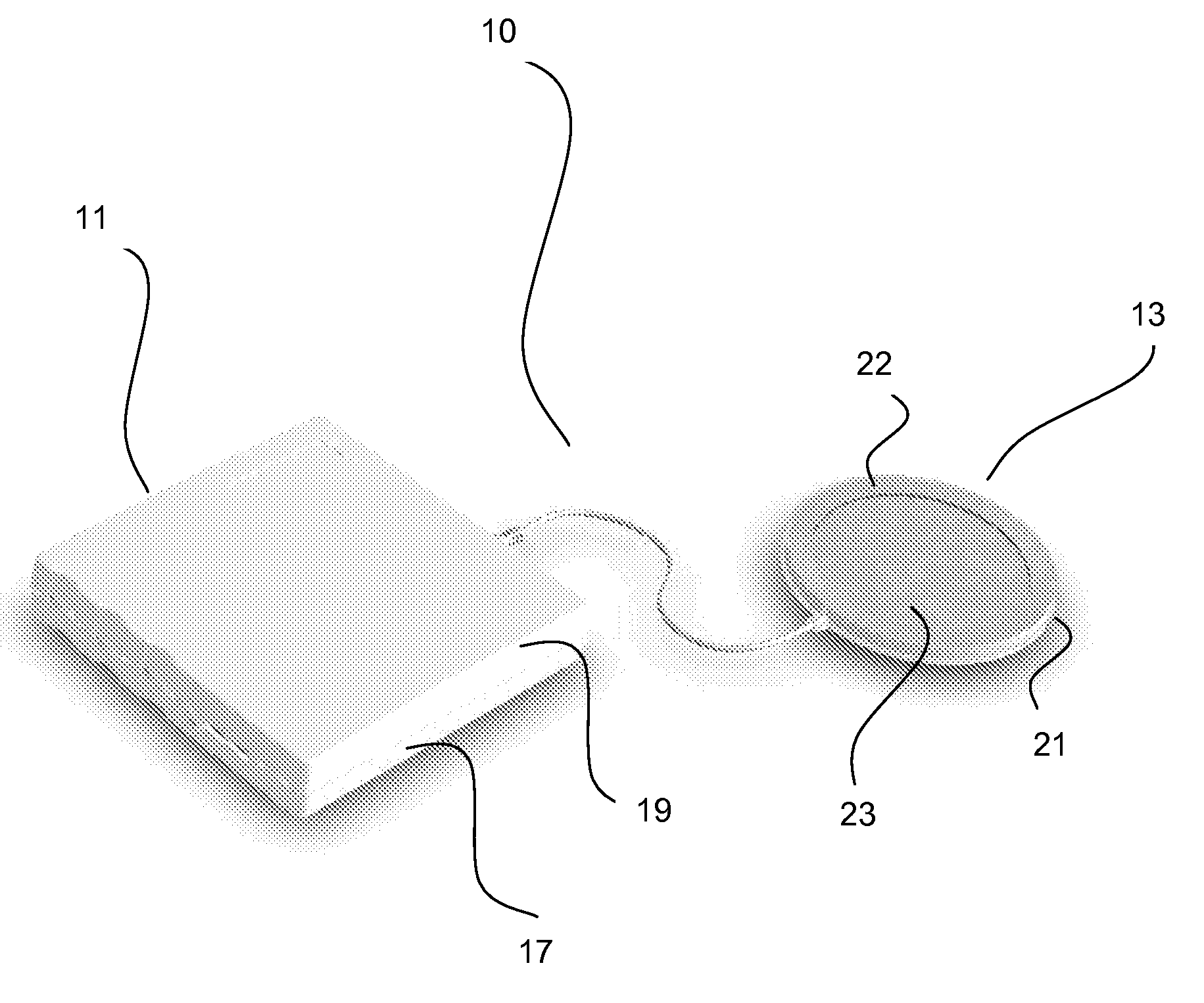
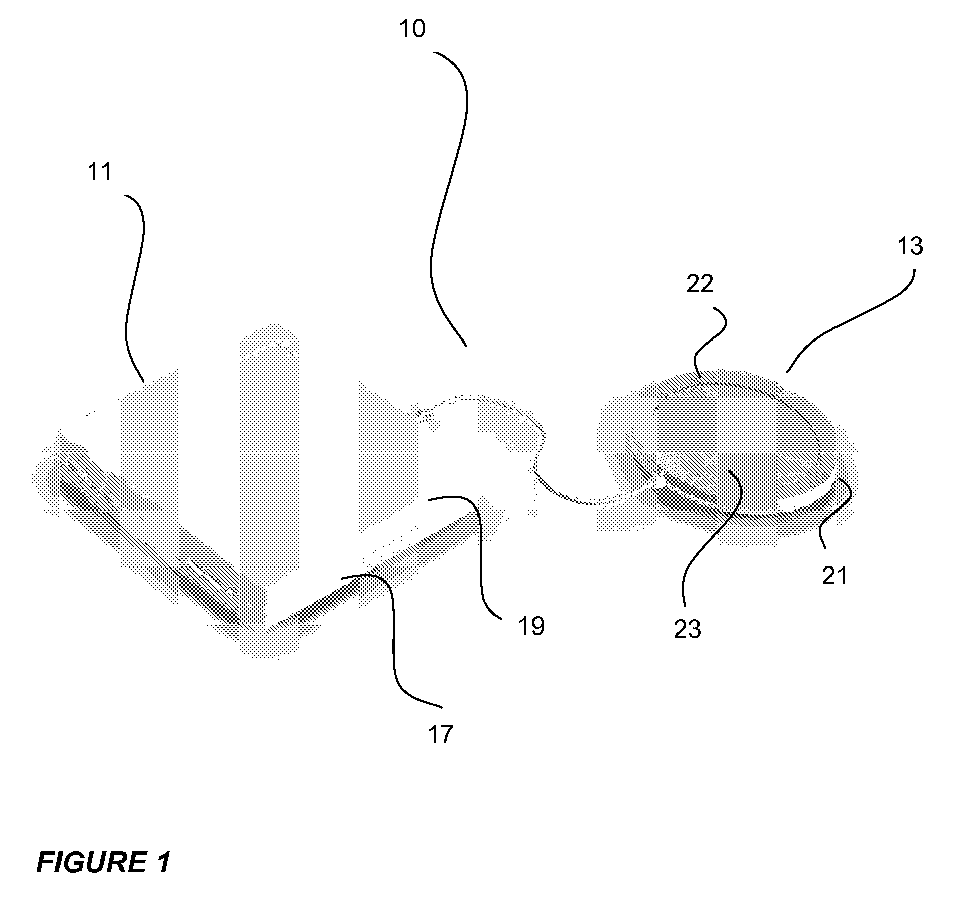
[0009] It is a primary object of the present invention to provide a low profile lighting system which enhances visual perception of objects by varying brightness, intensity, or luminosity. The present invention is designed to overcome certain problems with well known lighting system such as those noted above.

Problems solved by technology

Lighting of art objects is considered critical because even a slight difference in direction or type of light can significantly alter viewers' perception of the artwork.
Nevertheless, the artwork is exposed to heat radiation in a gallery style lighting system.
Second, incandescent lighting is one of the traditional lighting systems used for picture lighting.
Although incandescent lights bring out the warm colors in an artwork such as the red, brown, orange, and yellow tones, they do not bring out blue, green, and violet tones.
Further, the artwork is exposed to excessive heat because light from an incandescent lamp is generated by heating the filament to “incandescence” i.e. to temperatures above 200 degrees celsius.
Third, fluorescent lights are sometimes used to light artwork.
Although fluorescent lamps produce less heat than incandescent lamps, they generate high amounts of damaging UV rays.
Another disadvantage with using fluorescent lamps to light artwork is that the lamps do not emit light across the entire color spectrum and therefore, do not bring out the true colors in an artwork.
However, MR lamps are not energy efficient when used in applications where directional lighting is not necessary.

Method used


Image

  • Low profile lighting system
  • Low profile lighting system
  • Low profile lighting system

Examples


Embodiment Construction

[0023] It is to be understood that the present invention is not limited to the particular methodology, compounds, materials, manufacturing techniques, uses, and applications, described herein, as these may vary. It is also to be understood that the terminology used herein is used for the purpose of describing particular embodiments only, and is not intended to limit the scope of the present invention. It must be noted that as used herein and in the appended claims, the singular forms “a,”“an,” and “the” include the plural reference unless the context clearly dictates otherwise. Thus, for example, a reference to “an element” is a reference to one or more elements and includes equivalents thereof known to those skilled in the art. Similarly, for another example, a reference to “a step” or “a means” is a reference to one or more steps or means and may include sub-steps and subservient means. All conjunctions used are to be understood in the most inclusive sense possible. Thus, the word...


PUM


Abstract

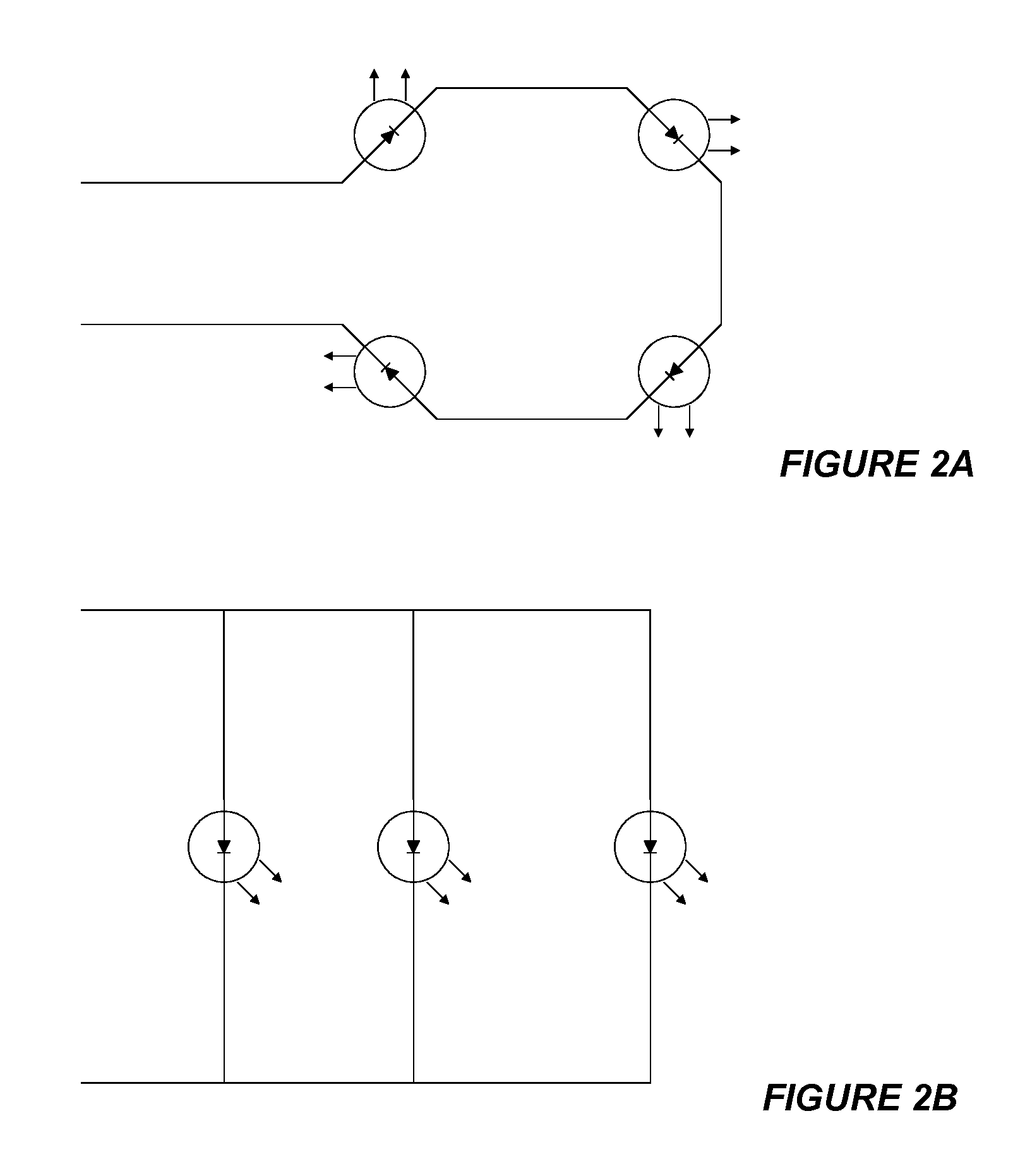
A low profile lighting system and method for illuminating objects for enhanced visual perception and for providing an energy-efficient and effective lighting system. The low profile lighting system comprises a first housing unit for housing an electronic unit, a second housing unit for housing at least one light source unit and at least one voltage supplier. The electronic unit, the light source unit(s), and the voltage supplier(s) are all electrically connected. The light source unit further comprises a plurality of light emitting diodes (LEDs) connected in series to form different configurations. Additionally, the intensity, luminosity, and brightness of the light output from the light source unit is adjustable between a predetermined maximum and minimum value for producing safe light over an object.

Description

CROSS REFERENCE TO RELATED APPLICATIONS [0001] The present application claims the benefit under 35 U.S.C. §119(e) of U.S. Provisional Application No. 60 / 730,328 filed Oct. 25 2005.FIELD OF THE INVENTION [0002] The present invention relates generally to lighting systems and, more particularly to a low profile lighting system which enhances visual perception of such objects by varying brightness, intensity, or luminosity. The present invention also relates generally to a method of lighting objects and, more particularly to a method of low profile lighting by placing the light source behind, beneath, beside or on top the object, directing the light from the light source onto the object and setting the intensity, luminosity, and brightness of the light source. BACKGROUND OF THE INVENTION [0003] Illumination of objects of art is pleasing because it enhances visual perception by complimenting the contents of the art objects. Art lighting allows objects of art to come alive with their true...

Claims


Application Information

Patent Timeline
IPC IPC(8): F21V15/00
CPCF21Y2101/02F21V23/00F21Y2115/10
Inventor SANNER, SUSAN H.CARRUTHERS, JOHN S.
Owner SANNER SUSAN H
Learn More