
Methods and apparatus for movable machining tools, including for wall saws

a machining tool and wall saw technology, applied in the direction of manufacturing tools, metal sawing devices, saw chains, etc., can solve the problems of time-consuming and/or cumbersome assembly and disassembly, difficult or time-consuming use of movable machining equipment, and difficulty in blade change out, etc., to achieve the effect of convenient movement and us

Inactive Publication Date: 2007-07-19
HUSQVARNA OUTDOOR PROD INC
View PDF31 Cites 66 Cited by
  • Summary
  • Abstract
  • Description
  • Claims
  • Application Information

AI Technical Summary

Benefits of technology

[0006]Movable machining equipment, for example wall saws, can be easier to move and use by being lighter, more compact or by being operable over a wider range of conditions or environments. In some instances, for example in some wall saw jobs, the equipment can be operated with larger blades from the beginning of the job without needing as many blade changes, or any needed blade changes can be made easier.
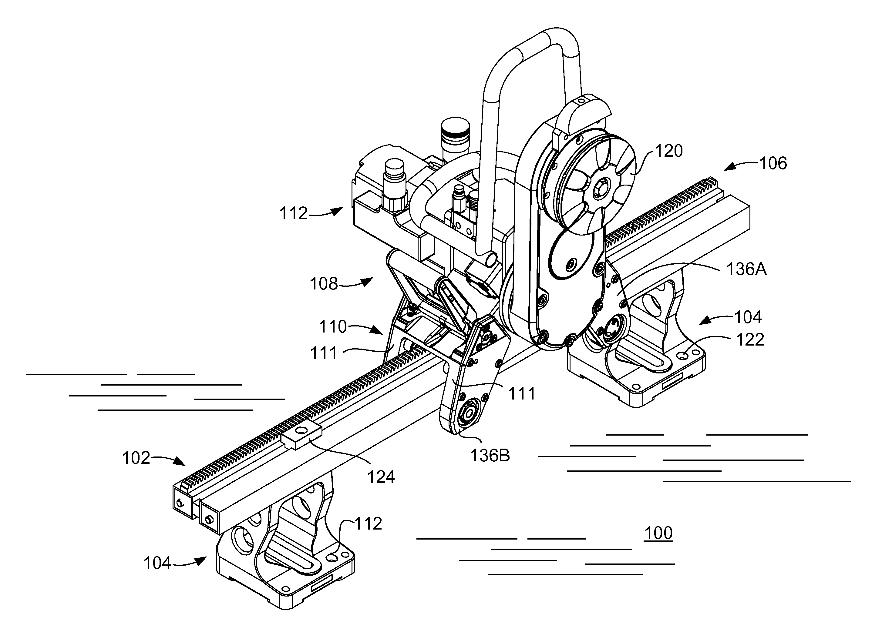
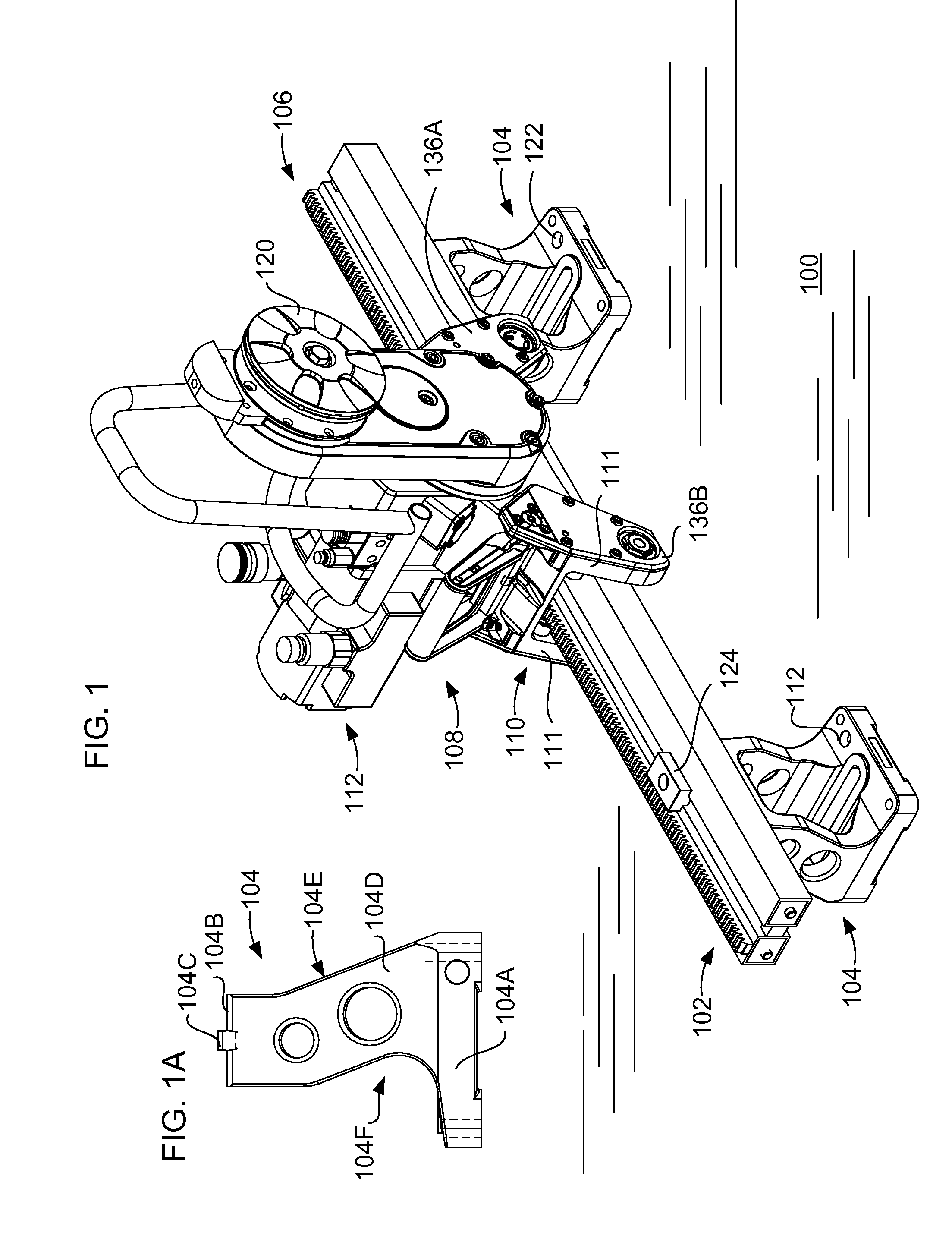
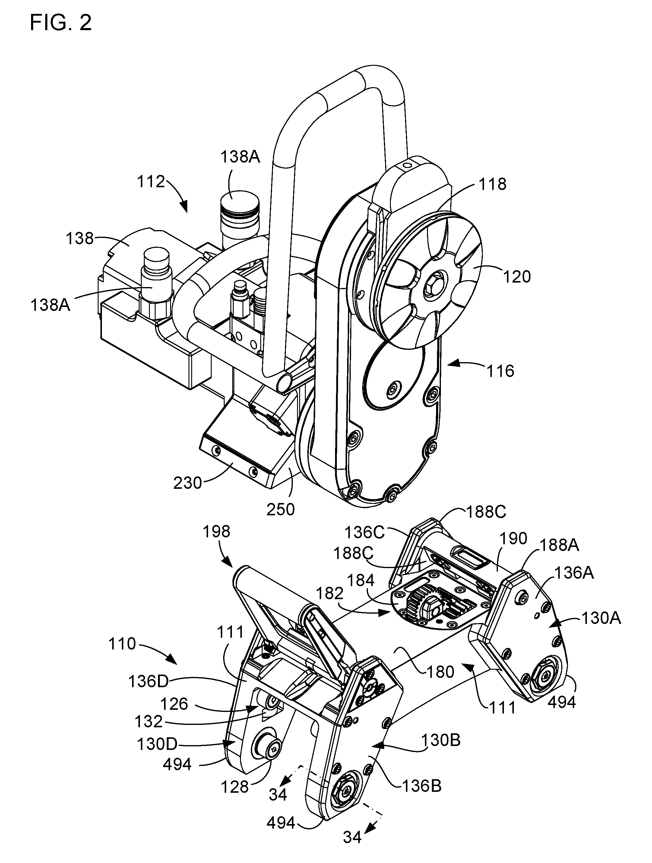
[0009]In a further example of a movable machining element, in one example a wall saw, a carriage is for moving along a surface and supports a cutting head in such a way that the head is removably mounted on the carriage. The cutting head and carriage have surfaces that engage each other and one of the engagement surfaces is movable into contact with its corresponding engagement surface and they are held in engagement with each other without having to thread or un-thread a threaded element, for example a nut or a bolt. In one configuration, a movable element is supported by the carriage and has a second surface at least partly complementary to a first surface on the carriage and wherein the two surfaces are relatively movable into and out of engagement with each other between an operating configuration and a separated configuration without the use of threads or a threaded engagement, such as those using multiple rotations to thread or un-thread a fastening bolt. In one example, a cutting head is movable into engagement with the carriage along a plane parallel to a plane of the cutting blade. In this example, drive gears for the carriage may also move in a plane parallel to the cutting blade, which orientations allows easier engagement between the cutting head and its drive gear on one hand, and the corresponding driven gear in the carriage on the other hand. In another example, the cutting head may move laterally into engagement with the carriage. In one configuration for lateral movement, the cutting head can move straight sideways into engagement with holding surfaces keeping the head from lifting off the carriage, and the cutting head can be kept from backing out by a locking pin, slide or other blocking element. In another configuration for lateral movement, the cutting head can have a first portion engaging the carriage and another portion pivoting sideways into engagement with the carriage, for example under a cantilever, ledge or other structure preventing upward movement of the cutting head. The cutting head would be held in place by a locking pin, slide or other blocking element keeping the cutting head from pivoting out of engagement with the carriage. The first portion of the cutting head could engage the carriage through a pivot pin, or other pivot-enabled link.

Problems solved by technology

Movable machining equipment can be heavy and sometimes difficult or time-consuming to assemble and / or maneuver for use.
In other equipment where the transport and machining mechanisms are more easily separable, the two mechanisms can be stored or moved to a job site as separate components and then assembled for use, but assembly and disassembly can be time-consuming and / or cumbersome.
This blade change out can be more difficult when the saw is mounted on a wall or on a ceiling.
In another example, the operator may need to reorient the saw relative to the cutting surface to finish the job, which also can be cumbersome or time-consuming.

Method used


Image

  • Methods and apparatus for movable machining tools, including for wall saws
  • Methods and apparatus for movable machining tools, including for wall saws
  • Methods and apparatus for movable machining tools, including for wall saws

Examples


Embodiment Construction

[0069]This specification taken in conjunction with the drawings sets forth examples of apparatus and methods incorporating one or more aspects of the present inventions in such a manner that any person skilled in the art can make and use the inventions. The examples provide the best modes contemplated for carrying out the inventions, although it should be understood that various modifications can be accomplished within the parameters of the present inventions.

[0070]Examples of machining tools and of methods of making and using the machining tools are described. Depending on what feature or features are incorporated in a given structure or a given method, benefits can be achieved in the structure or the method. For example, tools using carriages with removable driving heads may be easier to use and maintain. They may also take less time in set up, break down and during normal operation. Additionally, some machining tool configurations may also benefit from lighter-weight components, ...


PUM

PropertyMeasurementUnit
Angleaaaaaaaaaa
Widthaaaaaaaaaa
Circumferenceaaaaaaaaaa

Abstract

A movable machining element, for example a wall saw, can have one or more characteristics including a reversible driving head, a driving head removable from a carriage and having a quick release or quick lock mechanism, a driving head that is removable from a carriage without the use of threaded fasteners or having to unthread a holding element for removing the driving head from the carriage, a driving head with parallel, concentric or coaxial travel elements and tool driving elements, a tool driving assembly including a travel gear accessible from more than one direction, a component in the machining element having an oriented fiber or other composite incorporated in or as part of the component, an eccentric lateral adjustment assembly, or a drive shaft having a non-circular driving surface, for example a hexagonal drive shaft. In a wall saw, a blade and blade flange assembly are easily assembled on the saw or removed from the saw.

Description

BACKGROUND[0001]1. Field[0002]This relates to movable machining equipment, in one example wall saws.[0003]2. Related Art[0004]Movable machining equipment can be heavy and sometimes difficult or time-consuming to assemble and / or maneuver for use. In some equipment, that have powered transport or movement mechanisms, the transport mechanisms are incorporated in the structures that drive the machining mechanisms, so that the transport mechanisms and the machining mechanisms are effectively integrated into a single unit. In other equipment where the transport and machining mechanisms are more easily separable, the two mechanisms can be stored or moved to a job site as separate components and then assembled for use, but assembly and disassembly can be time-consuming and / or cumbersome.[0005]With some movable machining equipment, for example wall saws, operators may need to make adjustments part way through a given job. For example, when cutting an opening in a concrete wall, thick walls m...

Claims


Application Information

Patent Timeline
IPC IPC(8): B26D1/00
CPCB23D47/02B28D1/045B23Q9/0042Y10T83/9372Y10T83/929
Inventor BARATTA, ANTHONYJONSSON, ANDREAS
Owner HUSQVARNA OUTDOOR PROD INC
Learn More