
Dual purpose acute and home treatment dialysis machine

a dialysis machine and dual-purpose technology, applied in the field of dialysis machines, can solve the problems of limiting the ability of a user to modify prescriptions and machine settings that could harm the patient, physician or clinician will not be permitted to adjust, and the possibility of self-inflicted harm, so as to minimize the risk of disclosure, minimize the effect of manual entry mistakes and reduce the potential for self-inflicted harm

Inactive Publication Date: 2007-07-12
RENAL SOLUTIONS
View PDF22 Cites 94 Cited by
  • Summary
  • Abstract
  • Description
  • Claims
  • Application Information

AI Technical Summary

Benefits of technology

[0012] The difference between the home and acute modes of operation is the level of control of the dialysis machine that is allowed. In the clinical setting, a doctor or clinician needs flexibility in adjusting the machine, but in the home a user's control is restricted to reduce the potential for self-inflicted harm. Physicians and clinicians, for example, need to be able to modify prescription information and adjust machine settings in areas that could cause harm to a patient. The home use mode, on the other hand, restricts the ability of a user to modify prescription and machine settings that could harm the patient. Additionally, privacy concerns in a clinical setting may mandate that a patient's personal information stored in memory should be deleted as soon as that user has ceased using the machine. This information should also be deleted to prevent a situation where the prescription data is not updated for a new patient. In a home setting, however, such personal information can be retained because the risk of disclosure is minimized. Retaining such information in the home use setting also minimizes manual entry mistakes.

Problems solved by technology

In the clinical setting, a doctor or clinician needs flexibility in adjusting the machine, but in the home a user's control is restricted to reduce the potential for self-inflicted harm.
The home use mode, on the other hand, restricts the ability of a user to modify prescription and machine settings that could harm the patient.
Again, some parameters that a physician or clinician will be permitted to adjust will not be available to the home user or the ranges over which parameters can be adjusted will be limited for the home user.

Method used


Image

  • Dual purpose acute and home treatment dialysis machine
  • Dual purpose acute and home treatment dialysis machine
  • Dual purpose acute and home treatment dialysis machine

Examples


Embodiment Construction

[0018] The dialysis system shown schematically in the drawings has parts that are examples of the elements recited in the apparatus claims, and can be operated in steps that are examples of the elements recited in the method claims. The illustrated system thus includes examples of how a person of ordinary skill in the art can make and use the claimed invention. They are described here to meet the enablement and best mode requirements of the patent statute without imposing limitations that are not recited in the claims.

[0019] The invention encompasses a method of allowing a dialysis machine of the type shown in FIG. 1 to be set up for either a home setting or an acute setting such as a hospital or dialysis clinic.

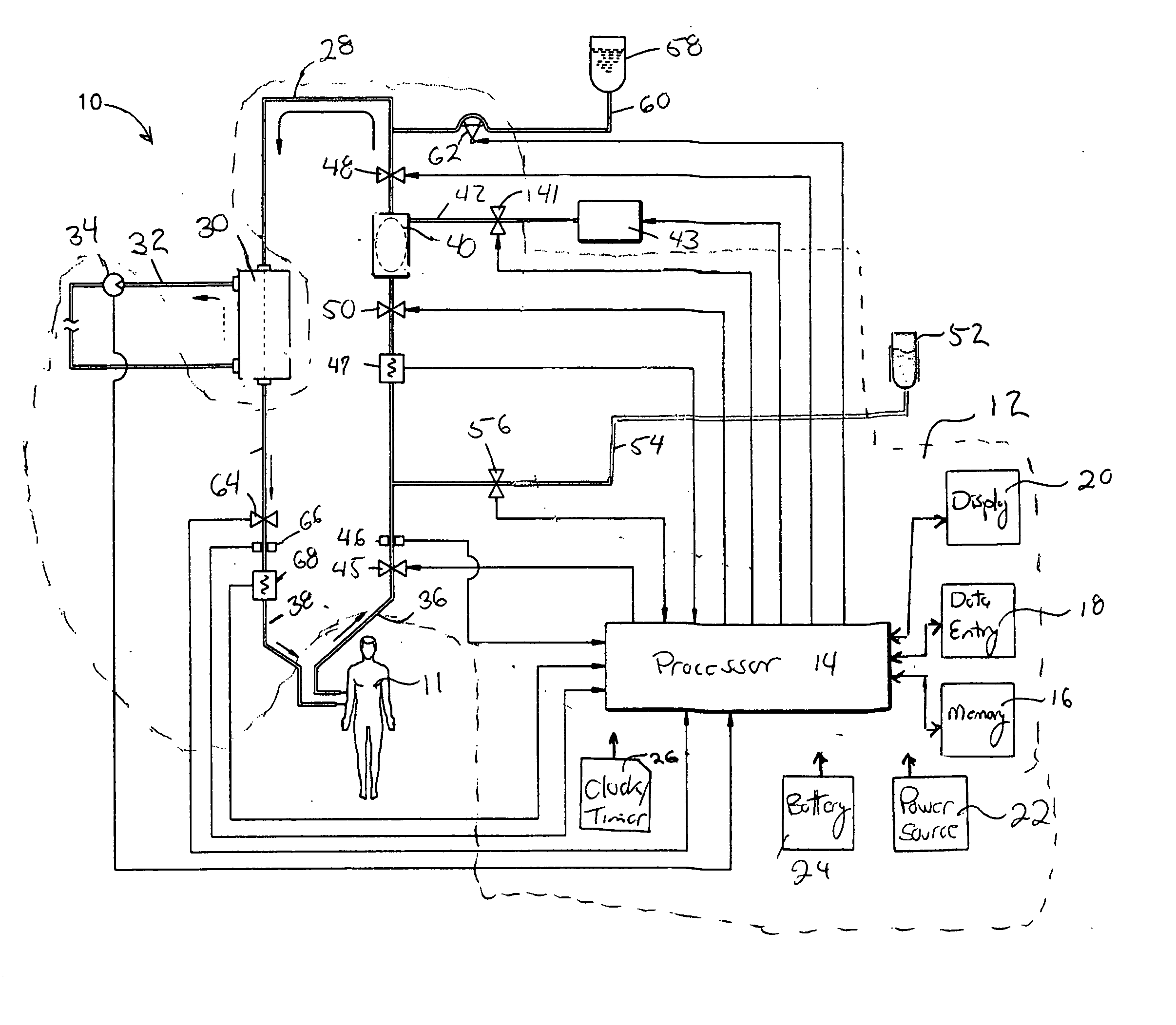
[0020]FIG. 1 is a schematic of a dialysis system 10 of the present invention. Referring to FIG. 1, the system 10 is a renal dialysis system for the extracorporeal treatment of blood from a patient 11 whose kidney function is impaired. The illustrated embodiment of the dial...


PUM


Abstract

A method of operating a dialysis machine comprising receiving patient specific data, storing the received patient specific data in a non-volatile memory device, and implementing a treatment according to one of an acute care mode or a home care mode is disclosed. In the case of the acute care mode of treatment, the patient specific data is deleted after implementing the treatment. In the case of the home care mode of treatment, the patient specific data is retained after implementing the treatment. Hardware for implementing the disclosed method is also disclosed. Because of the rules governing abstracts, this abstract should no be used to construe the claims.

Description

[0001] The present invention claims priority from U.S. Application Ser. No. 60 / 757,052 filed Jan. 6, 2006 and entitled Dual Purpose Acute and Home treatment Dialysis Machine, the entirety of which is hereby incorporated by reference.BACKGROUND [0002] The present invention relates to a dialysis machine for extracorporeal treatment of blood. More particularly, the invention relates to a dialysis machine that provides distinct modes of operation, e.g., a home setting or an acute setting (e.g., a hospital or dialysis clinic). [0003] Various types of medical equipment are designed with the knowledge that the equipment may be used in an ambulatory manner. For example, U.S. Pat. No. 5,317,506 issued to Coutre et al. and entitled Infusion Fluid Management System discloses an infusion management and pumping system. Infusion prescriptions are generated and monitored by a pharmacy management system. Labels for each infusion to be given to a patient are generated and printed in a bar code forma...

Claims


Application Information

Patent Timeline
Patent Type & Authority Applications(United States)
IPC IPC(8): B01D61/00
CPCA61M1/16A61M2205/505A61M2205/502A61M2205/3393
Inventor DECOMO, PETER
Owner RENAL SOLUTIONS
Learn More