Communication control unit
a communication control and unit technology, applied in the field of acquisition of telephone status, can solve the problems of service level gap between users and the inability to use ultramodern coordination systems
- Summary
- Abstract
- Description
- Claims
- Application Information
AI Technical Summary
Benefits of technology
Problems solved by technology
Method used
Image


Examples
embodiment 1
[0034]In this embodiment, first, the physical construction, logical construction and operational overview of the telephone adapter of the invention, and an actual example of the network connections of a company office using this adapter, will be described. Next, referring to flowcharts, specific examples of the usage of the telephone adapter of the invention, PC displays and messages, will be given.
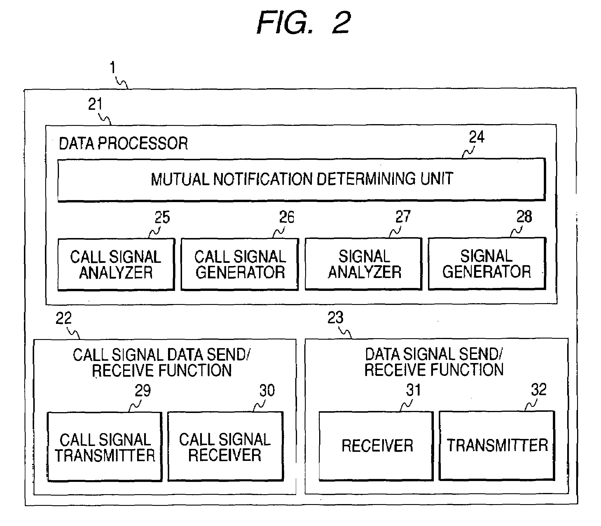
[0035]FIG. 1 shows the physical configuration of the telephone adapter of the invention. FIG. 2 shows a functional block diagram of the telephone adapter of the invention. The functional block diagram of FIG. 2 is a diagram showing the logical functions, but it will be understood that each functional block can be implemented either by software or hardware.
[0036]If the functional block shown in FIG. 2 is implemented by software, the processing contents are stored in a processing module set 6 in a memory 4 of FIG. 1, and when a function is executed, a CPU 3 calls these data via a data bus 7...
embodiment 2
[0071]FIG. 10, FIG. 11 show an example where the example of FIG. 7 is implemented by a telephone adapter of different form. In this example, the telephone adapter is not activated by a trigger on reception of a call signal. As shown in the lower diagram of FIG. 10, a receiver sensor 901 is disposed near a telephone hook 92, the sensor perceiving an up-down motion of the hook due to a receiver 903, and a trigger is issued when the receiver moves up and down. The physical structure of the telephone adapter, together with this mechanism, is as shown in the upper diagram of FIG. 10. The difference from FIG. 1 is that, instead of the call signal processing unit 2, call signal IF (PBX side) 8 and call signal IF (terminal side) 9 of FIG. 1, a receiver sensor 151 is provided to handle the function of signal processing.
[0072]FIG. 11 is a sequence diagram of this example. The operation of this example will now be described following this sequence. A step 161 to a step 164 are identical to tho...
embodiment 3
[0076]FIG. 12 is a sequence diagram showing a second application of the invention. FIG. 12 shows an example where, when there is a call to a telephone terminal managed by a telephone adapter, each telephone adapter sends this information to the presence send-receive server, and surrounding users can determine which telephone terminal bell is ringing. This example will now be described by following the sequence. This example applies to the network connections shown in FIG. 4. In this example, a trigger is generated from the call signal side as shown in FIG. 5, and the telephone adapter functions “when there is a telephone call”.
[0077]In this example, first in a step 181, the data terminal of User B logs in to the presence send-receive server 52. Next, it subscribes to its own floor ID. For example, if its location is 3F, Room No. 301, a subscription is made to this ID. It is thus possible to receive presence data as to the part where the telephone is ringing. Next, in a step 183, if ...
PUM
 Abstract
Description
Claims
Application Information
 - R&D
- Intellectual Property
- Life Sciences
- Materials
- Tech Scout
- Unparalleled Data Quality
- Higher Quality Content
- 60% Fewer Hallucinations
Browse by: Latest US Patents, China's latest patents, Technical Efficacy Thesaurus, Application Domain, Technology Topic, Popular Technical Reports.
© 2025 PatSnap. All rights reserved.Legal|Privacy policy|Modern Slavery Act Transparency Statement|Sitemap|About US| Contact US: help@patsnap.com