
Zoom optical system

a technology of optical system and zoom factor, applied in the field of zoom optical system, can solve the problems of lack of robustness, large volume of this type of optical system, and high cost of methods,

Inactive Publication Date: 2007-07-05
KONINKLIJKE PHILIPS ELECTRONICS NV
View PDF5 Cites 25 Cited by
  • Summary
  • Abstract
  • Description
  • Claims
  • Application Information

AI Technical Summary

Benefits of technology

[0009] It is an object of the present invention to provide a zoom optical system having improvements to the zoom function for a captured image whilst reducing the need for mechanical components in the optical system.
[0014] A zoom optical system may be produced according to the present invention which is relatively simple, compact, inexpensive and robust.
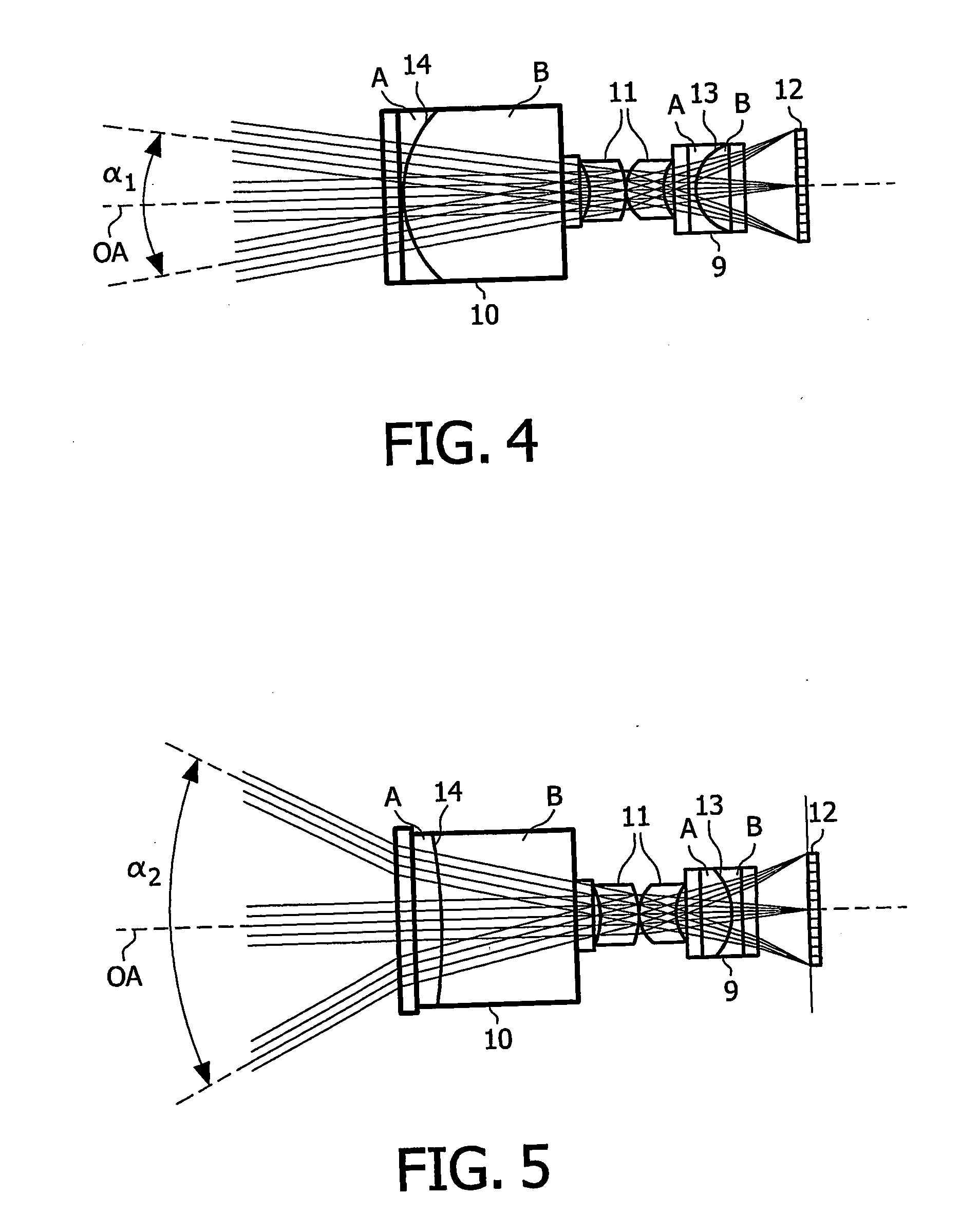
[0017] In an embodiment of the present invention the lens system preferably comprises a further switchable optical element which is arranged to operate in cooperation with the switchable optical element to provide at least part of the variable zoom setting of the lens system. With the lens system comprising a further switchable optical element which operates cooperatively with the other switchable optical element, the zoom optical system is able to provide a binary zoom functionality whilst maintaining a fixed focus. By having a fixed focus, such a binary zoom optical system may be constructed which is relatively compact in size.
[0021] Preferably, the first fluid is a liquid and the second fluid is gaseous. The term gaseous includes either of a gas mixed with a vapour of a liquid, or only a gas. This is possible since the two fluids do not need to be density matched, even if the device is to be used in various orientations, and has the advantage that a relatively large difference in refractive index between the two fluids is provided.

Problems solved by technology

Zoom optical systems of this type are however relatively bulky and mechanically complex.
Movement of the different lenses may be performed either manually or automatically, but these methods are typically relatively expensive and lacking in robustness.
An increase in an upper limit of the zoom factor range of a zoom optical system of this type will generally increase the bulk and complexity of the zoom optical system.
This is a relatively slow and inconvenient process and requires a camera user to carry different lenses in addition to the camera.
Since the refractive indices of the two liquids are not greatly different, and because the extent to which the curvature may be varied is limited, the optical power range of the fluid meniscus lenses is relatively small.
This imposes a limit on the possible zoom factor range provided by the zoom optical system.
In particular, one lens component in a zoom lens system (typically that closest the image capture device) requires the greatest optical power range during zooming, so the amount of zooming is constrained by the relatively limited optical power range of the fluid meniscus lens used as that one lens component.

Method used


Image

  • Zoom optical system
  • Zoom optical system
  • Zoom optical system

Examples


Embodiment Construction

)

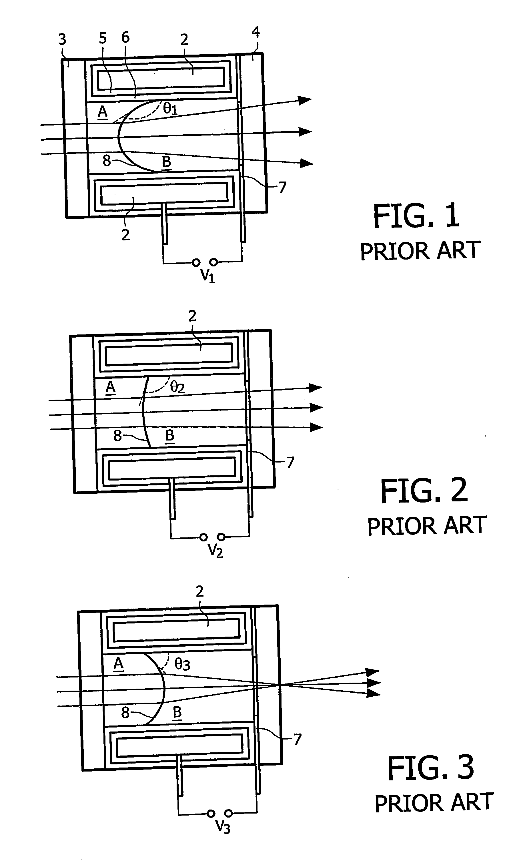
[0035] FIGS. 1 to 3 show, in accordance with the prior art, a variable focus lens which is a fluid meniscus lens comprising a cylindrical first meniscus electrode 2 forming a capillary tube, sealed by means of a transparent front element 3 and a transparent back element 4 to form a fluid chamber containing two different fluids. The first meniscus electrode 2 may be a conducting coating applied on the inner wall of a tube.

[0036] The two different fluids consist of two non-miscible liquids in the form of an electrically insulating first liquid A, such as a silicone oil or an alkane, referred to herein further as “the oil”, and an electrically conducting second liquid B, such as water containing a salt solution. The two liquids are preferably arranged to have an equal density, so that the shape of the meniscus can be controlled independently of orientation, i.e. without dependence on gravitational effects between the two liquids. This may be achieved by appropriate selection of the f...


PUM


Abstract

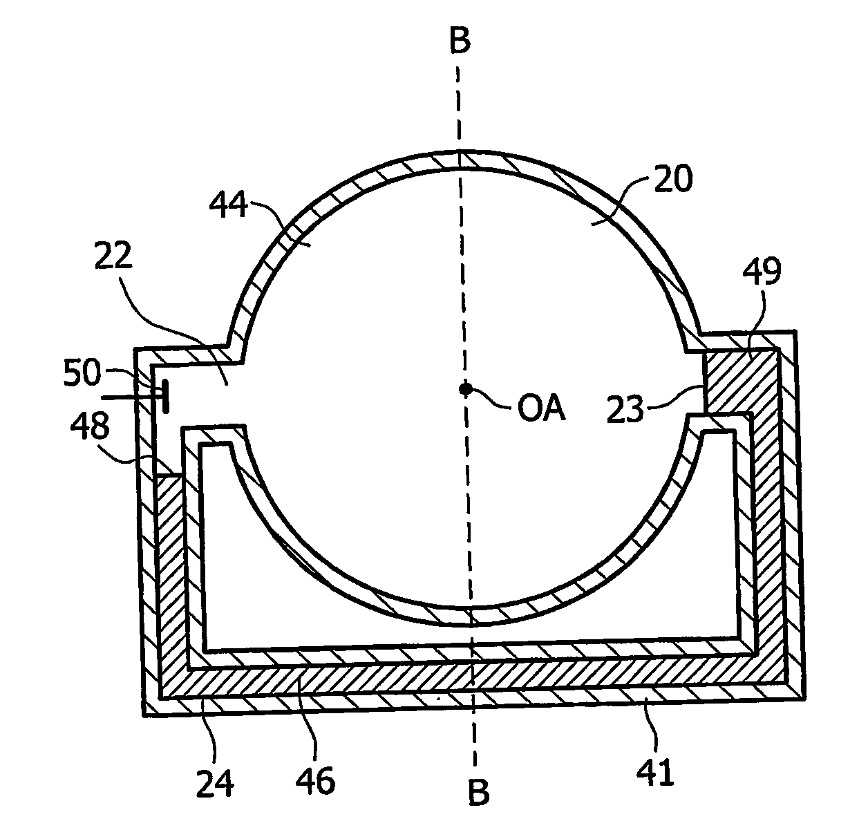
A zoom optical system is provided which has a lens system which comprises a first lens which is arranged to provide a continuously variable focus for a beam of radiation. The lens system further comprises a switchable optical element including a first fluid, a second fluid and a wavefront modifier having a part through which said radiation beam is arranged to pass. In a first mode the switchable optical element has a first fluid configuration with said part being substantially covered by the first fluid, and in a second mode the switchable optical element has a second, different, fluid configuration with said part being substantially covered by the second fluid.

Description

TECHNICAL FIELD [0001] The present invention relates to a zoom optical system, particularly but not exclusively for use in an image capturing apparatus. BACKGROUND ART [0002] Often when capturing an image of an object using an image capturing apparatus, for example a camera, it is desirable to be able to change a zoom setting for the image. With the distance between the camera and the object remaining constant, a high zoom factor allows an image of the object to be captured at a high level of magnification and a narrow field of view. A low zoom factor allows an image of the object to be captured at a low level of magnification and a wide field of view. In the example of a camera the high zoom factor is characteristic of a telephoto lens setting and the low zoom factor is characteristic of a wide-angle lens setting. [0003] Different zoom factors require different effective focal lengths of a zoom optical system. For a telephoto lens setting the effective focal length is relatively lo...

Claims


Application Information

Patent Timeline
IPC IPC(8): G02B3/12G02B15/14G02B3/14G02B15/00G02B26/02
CPCG02B3/14G02B26/005G02B15/00G02B3/12
Inventor HENDRIKS, BERNARDUS H.W.KUIPER, STEIN
Owner KONINKLIJKE PHILIPS ELECTRONICS NV
Learn More