
Tree stand

a tree stand and loop technology, applied in the field of tree stands, can solve the problems of difficulty in shortening the loop and particularly difficul

Inactive Publication Date: 2007-07-05
FORREST LEWIS
View PDF11 Cites 0 Cited by
  • Summary
  • Abstract
  • Description
  • Claims
  • Application Information

AI Technical Summary

Benefits of technology

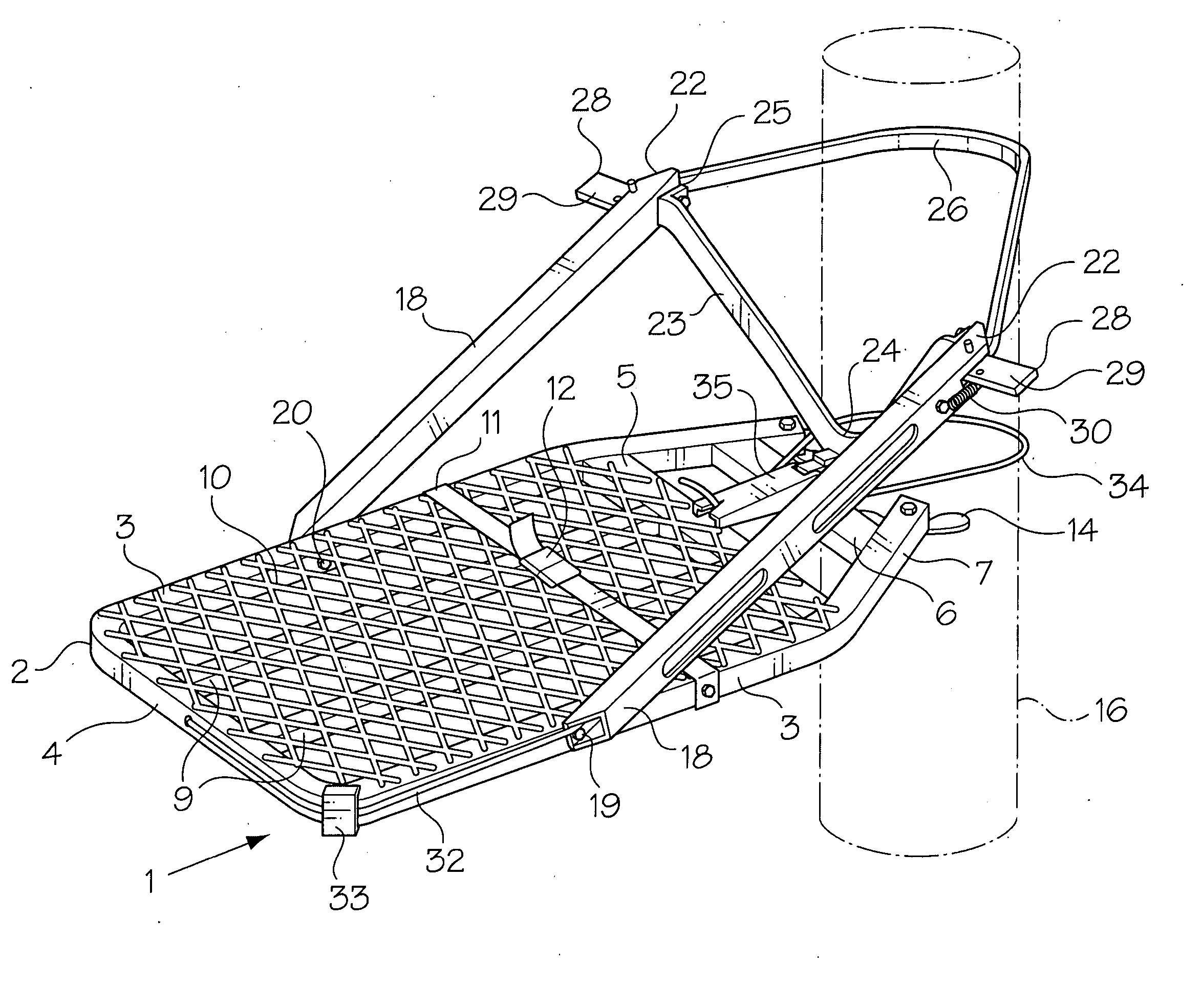
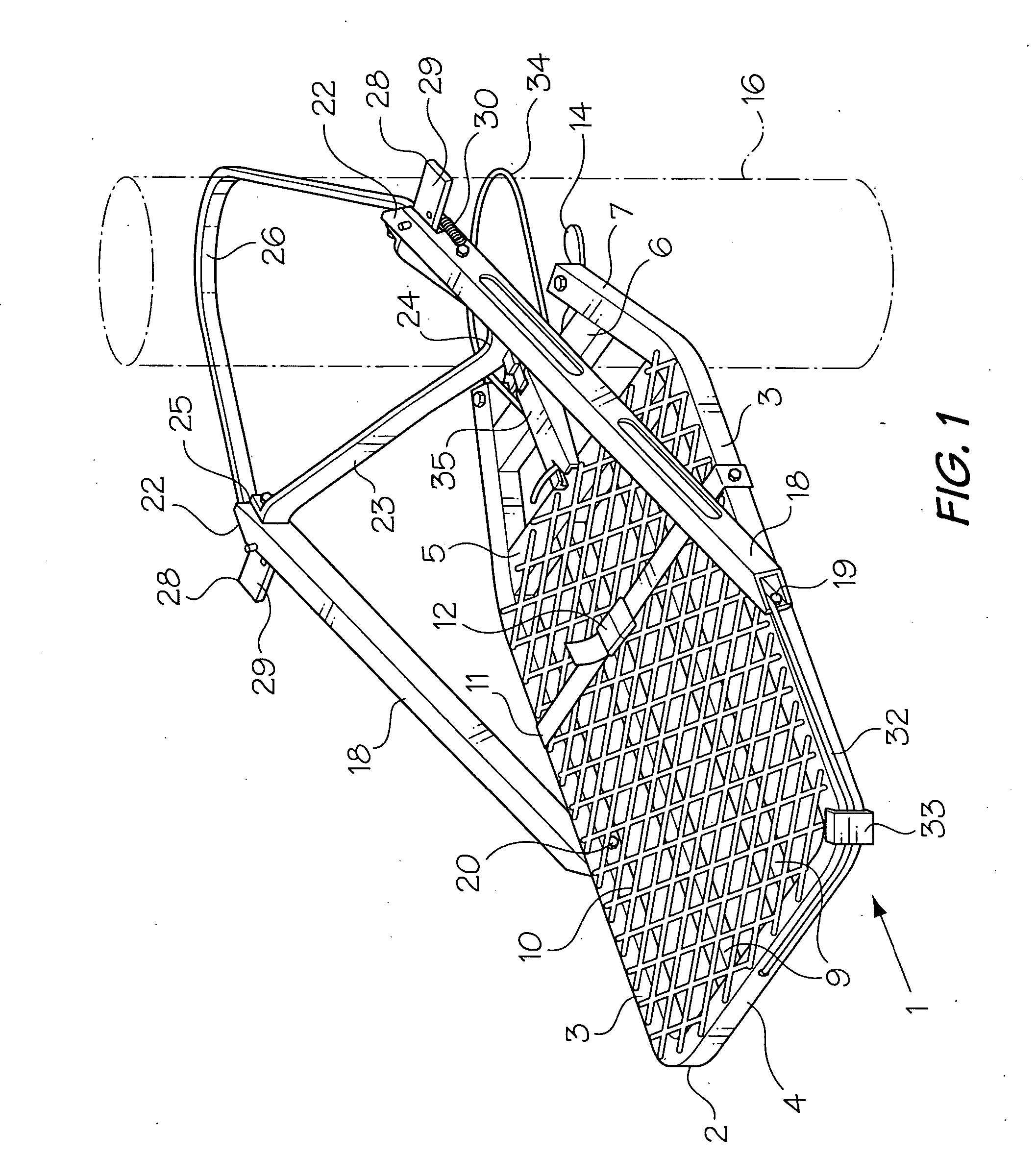
[0007] The object of the present invention is to provide a solution to the above-mentioned problem in the form of a relatively simple mechanism, which facilitates shortening of the belt used to hold a stand on a tree.

Problems solved by technology

A problem with existing stands is the difficulty in making the loop shorter as the trunk becomes narrower.
This is particularly difficult when shortening the belt on the lower platform.

Method used


Image

  • Tree stand
  • Tree stand
  • Tree stand

Examples


second embodiment

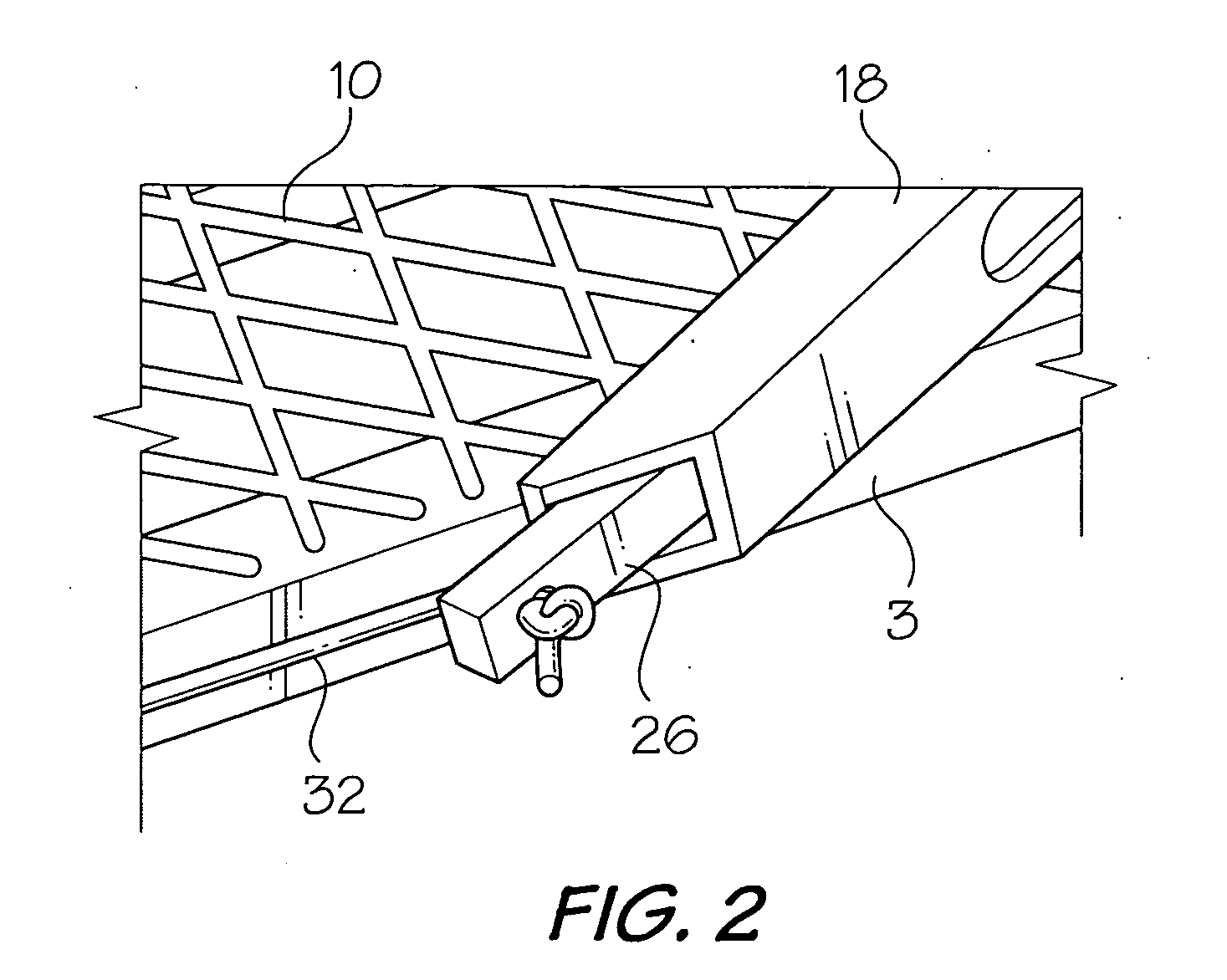
[0021] Referring to FIGS. 3 and 4, in the invention, th extensible cord 32 is mounted in one of the support arms 18. Both free ends 36 of the cord 32 are connected to the top end of the arm 18 by a bolt 38. The cord 32 extends though a slot 39, which receives the latch lever 28, into the support arm 18. The cord 32 extends downwardly through the arm 18 around a sleeve 40 on a bolt 41 at the bottom end of the arm 18, through a hole 42 (FIG. 3) in the bottom end of the belt 26, back around the sleeve 40, and up through the arm 18 and the slot 39 to the bolt 38.

third embodiment

[0022] In a third embodiment fo the invention (FIG. 5), the cord 32 extends from the bolt 38, through the slot 39, downwardly through the support arm 18, around the sleeve 40, through the belt 26, and upwardly through the arm 18 and the slot 39 to the bolt 38.

[0023] It will be appreciated that while the belt 26 is preferably an ordinary V-belt or the like, the belt can also be a chain or a cable. Moreover, the bungee cord illustrated in the drawings can be replaced by a helical spring or any other extensible, resilient element.


PUM


Abstract

A tree stand includes a platform having a tree engaging end; a pair of hollow support arms pivotally connected to the sides of the platform; a belt having ends slidable in the support arms for forming a loop around a tree trunk to connect the platform to the tree; latches on the arms for locking the ends of the belt in position; and a bungee cord or spring connecting one end of the belt to the platform or support arms, whereby when one latch is released the belt is pulled into one arm to shorten the loop around the tree.

Description

BACKGROUND OF THE INVENTION [0001] 1. Field of the Invention [0002] This invention relates to a tree stand, and in particular to a stand which can be used to climb and support a load in a tree. [0003] 2. Discussion of the Prior Art [0004] As described in the inventor's U.S. Pat. No. 6,588,546, issued Jul. 8, 2003, (which is incorporated herein by reference) tree stands are load supporting platforms used primarily by hunters. The stands are used to climb a tree and to support a hunter at an elevated position on the trunk of a tree. Most conventional tree stands are formed of two parts, including a top or seat platform and a bottom or footrest platform. Examples of such tree stands are disclosed by U.S. Pat. No. 4,488,620, issued to L. R. Gibson on Dec. 18, 1984; 4,589,522, issued to D. L. Shelton on May 10, 1986; U.S. Pat. No. 4,596,309, issued to J. W. Venson on Jun. 24, 1986; U.S. Pat. No. 4,942,942, issued to R. E. Bradley on Jul. 24, 1990; U.S. Pat. No. 5,097,925, issued to G. T....

Claims


Application Information

Patent Timeline
Patent Type & Authority Applications(United States)
IPC IPC(8): E04G3/00
CPCA01M31/02
Inventor FORREST, LEWIS
Owner FORREST LEWIS
Learn More