
Plank for Wall or Surface Covering and Methods Thereof

a technology for wall or surface covering and planks, applied in the field of building materials, can solve the problems of unsatisfactory nailing of planks, difficulty in properly and securely attaching planks to a wall or surface, and end users, and achieve the effect of improving performan

Active Publication Date: 2021-12-09
FULTS KEVIN
View PDF37 Cites 1 Cited by
  • Summary
  • Abstract
  • Description
  • Claims
  • Application Information

AI Technical Summary

Benefits of technology

The invention is a plank wall covering system and methods of manufacturing and use that improve upon existing systems. The plank has a flat front façade and a back member with multiple plateaus and concave channels that control the amount of construction adhesive applied. The size of the channel controls the amount of adhesive, and the end user applies adhesive only in the designated channels. The plank is formed from stiff material, such as wood, and can adapt to uneven surfaces for stronger and longer-lasting adhesion. The reclaimed lumber is processed to consistent dimensions and the channels and plateaus design limit the location and volume of adhesive applied. The plank is also configured with regulating delineations that facilitate shortening and relieve pressure within the wood fiber. Overall, the invention provides an improved performance over existing systems.

Problems solved by technology

However, properly and securely attaching planks to a wall or surface presents difficulties.
Nailing the planks is undesirable because not only do nail heads detract from the attractiveness of the natural wood grain or other exterior finish, but also the end user (retail customer or construction worker) cannot readily locate the studs (typically supporting the sheet rock wall structure) into which the nails should be driven.
Though this is convenient, and no nails or hammers are needed, this conventional peel-and-stick system does not provide a stable, long lasting bond; the planks tend to loosen and separate from the wall over time.
Using the peel-and-stick product in areas with high humidity or in areas that experience high temperatures only amplifies the problems to the degree that this conventional product is not satisfactory in all cases.
This liberal application wastes the adhesive product.
Therefore, it unnecessarily increases the cost of the installation, and it may result in excess adhesive being forced out from the back of the plank to mar the edges of the plank front or oozing out between adjacent planks, which then requires extra time and work for cleanup.

Method used


Image

  • Plank for Wall or Surface Covering and Methods Thereof
  • Plank for Wall or Surface Covering and Methods Thereof
  • Plank for Wall or Surface Covering and Methods Thereof

Examples


first embodiment

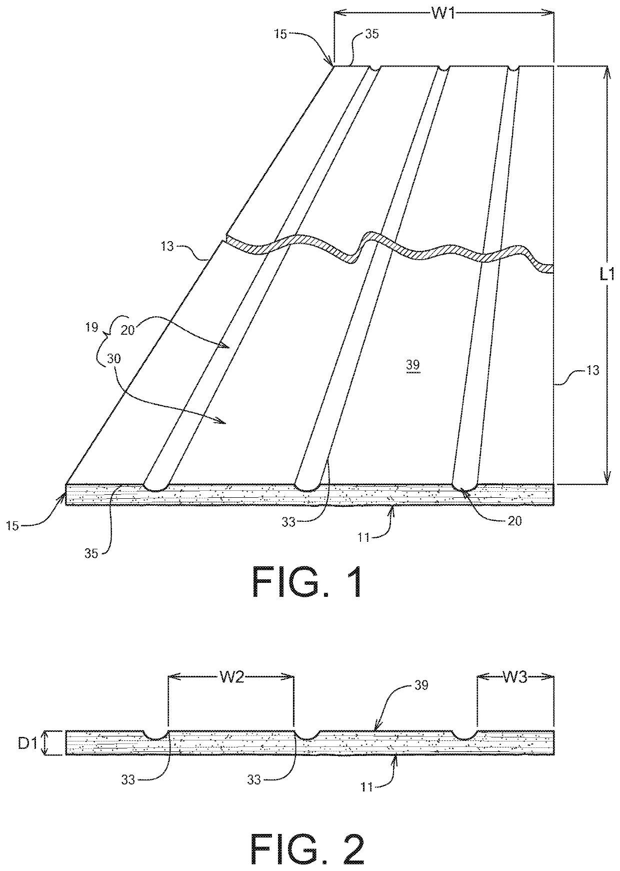
[0075]In FIGS. 1-2, the plank 10 includes three channels 20 disposed between four plateaus 30. The channels 20 are long, narrow U-shaped cuts or indentations in the back member 19 of the plank 10 that extend the length L1 of the plank 10. In this embodiment, each of the channels 20 have the same channel depth D2.

second embodiment

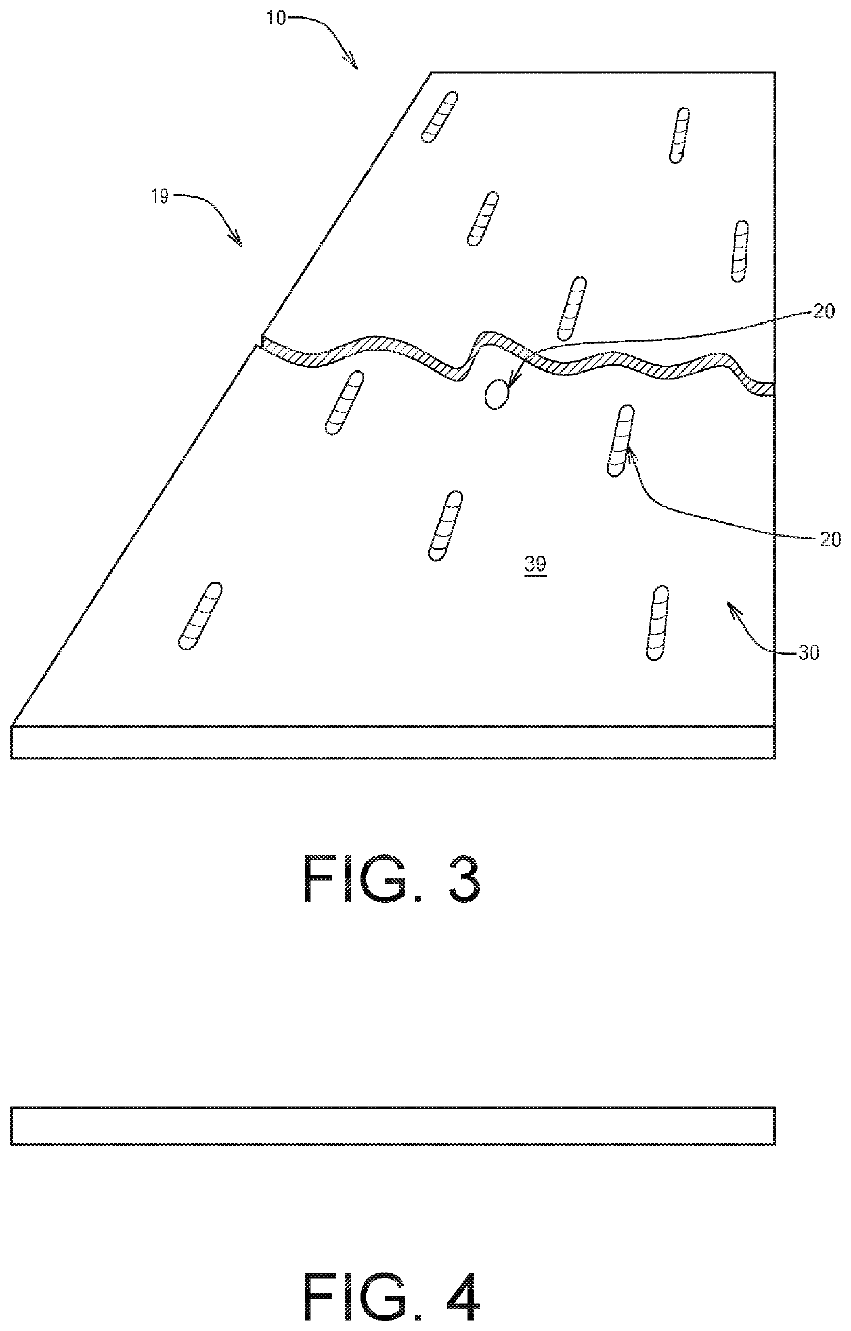
[0076]In FIGS. 3-4, the concave channels 20 do not extend the length of the plank, but instead they are concavities distributed periodically along the back member 19 of the plank 10. FIG. 3 shows that the channel 20 may take the form of a short, slender depression or may be in the shape of an oval trough or a circular concavity. These shaped channel designs are used to limit the amount and identify the location of the adhesive application. For example, in instances when the volume of a full-length channel (as shown in FIG. 1) defines a volume of adhesive that is greater than necessary or desirable, the fabricator of the plank can reduce the volume defined by the channel by using short linear, oval, or circular channels as shown in FIG. 3.

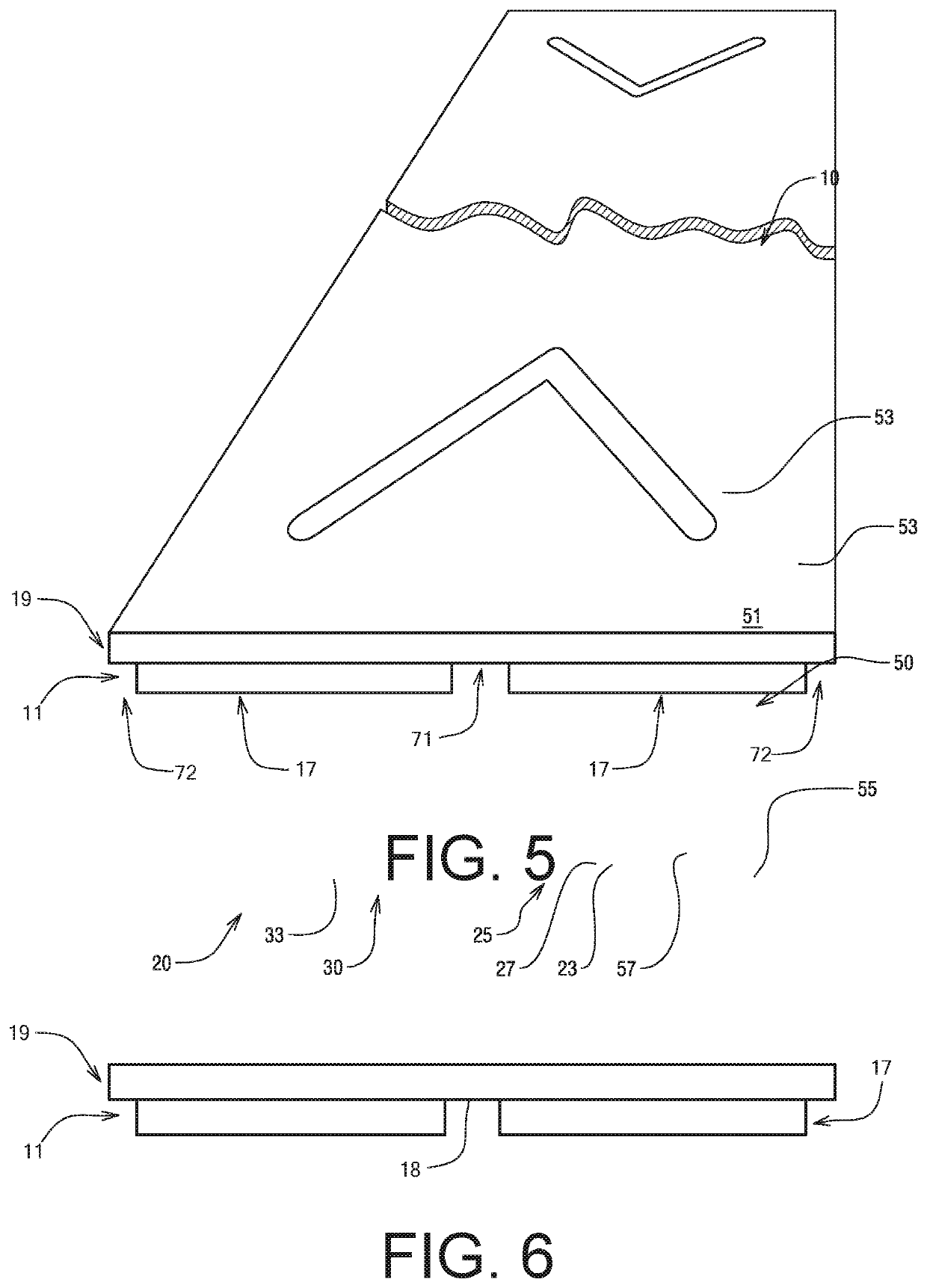
[0077]In the third embodiment of FIGS. 5-6, the concave channels 20 do not extend the length of the plank as in the first embodiment. Instead, the ends of two straight, narrow channels join together to form a V-like trough formation. One V-type chan...

seventh embodiment

[0091]the invention of FIGS. 18-24 discloses an enhanced plank 70, which, as in the earlier embodiments, comprises at least one plateau 30 and multiple channels 20. However, the enhanced plank 70 has a greater length and / or width than the plank 10 of the earlier embodiments. Therefore, a greater square footage of the wall or surface is covered when a single enhanced plank 70 is installed compared to the square footage covered by the smaller plank 10. Due to the larger coverage area, the enhanced plank 70 may provide advantages in speed and efficiency of installation, yet still provides guidance to the user by regulating and standardizing the location of adhesive application and the volume of adhesive that will be applied. Due to the greater length and width, which leads to a heavier piece, the façade 11 and the back member 19 may have a depth that is greater than the depth of the plank 10 of the earlier embodiments. As in the other embodiments, the façade 11 and the back member 19 m...


PUM


Abstract

A plank and plank system for covering a wall or other surface is provided. Each longitudinally extending plank comprises a generally planar front façade and a back member. The back member comprises multiple plateaus interspersed with channels. Each plateau provides a flat surface that will be adjacent to the wall / surface when the plank is installed and onto which, optionally, a strip of pressure sensitive adhesive tape may be applied. The channels provide a predetermined location and predetermined holding capacity to regulate the location and amount of construction adhesive to be applied by a user. In an aspect of the invention, the channels also provide a degree of flexibility that allows the plank to adhere securely to the wall and that allows the depth of the plank to be greater than conventional wood wall covering panels.

Description

CROSS-REFERENCE TO RELATED APPLICATIONS[0001]This nonprovisional application claims the benefit of co-pending U.S. Provisional Patent Application Ser. No. 63 / 034,918, filed on Jun. 4, 2020, which is incorporated herein in its entirety.FIELD OF INVENTION[0002]This invention relates generally to building materials, and, more particularly, to a plank of wood or of natural or synthetic material for covering walls or surfaces, to a fabrication system thereof, to installation thereof, and to fastening means thereof.BACKGROUND OF THE INVENTION[0003]Planks of milled lumber and / or of other natural materials and / or of synthetic materials may be used for covering walls or surfaces to provide both functional and aesthetic enhancement. However, properly and securely attaching planks to a wall or surface presents difficulties. Nailing the planks is undesirable because not only do nail heads detract from the attractiveness of the natural wood grain or other exterior finish, but also the end user (...

Claims


Application Information

Patent Timeline
Patent Type & Authority Applications(United States)
IPC IPC(8): E04F13/08
CPCE04F13/0887E04F13/0885E04F13/04E04F2203/02
Inventor FULTS, KEVIN
Owner FULTS KEVIN
Learn More