Cold crucible induction furnace with eddy current damping

a technology of eddy current damping and cold crucible, which is applied in the direction of furnaces, charge manipulation, lighting and heating apparatus, etc., can solve the problems of increasing conduction loss, increasing heat radiation loss from liquid, and intermittently disturbing the separation region between the walls, so as to selectively reduce the motion of the molten material

Inactive Publication Date: 2007-06-28
CONSARC
View PDF6 Cites 16 Cited by
  • Summary
  • Abstract
  • Description
  • Claims
  • Application Information

AI Technical Summary

Problems solved by technology

Fluid motions caused by induced currents can intermittently disturb the region of separation between the wall and the mass of liquid metal.
Such disturbances increase the boundary area of the melt, resulting in increased heat radiation losses from the liquid, or even increased conduction losses, if some of the liquid metal washes or splashes against the wall of the crucible.
However, the above apparatus and method has disadvantages when used to superheat the liquid metal.
This results in an increase in the heat transferred from the liquid metal to the skull.
Decreased skull thickness increases heat losses from the liquid melt.
Further the skull may be reduced in overall volume, so that parts of the liquid melt formerly contained within the skull can come into contact with the wall of the crucible, which greatly increases the heat loss from the liquid metal.
In practice, the result is that for any reasonable power input to the above apparatus and process, the superheat is severely limited.
However, locating a dc coil adjacent to the ac coil as proposed in the Bojarevics and Pericleous paper, would result in the ac magnetic field inducing high losses in the large cross sectional dc conductors shown in the paper.
Moreover, there is no recognition or analysis of this deleterious effect in the Bojarevics and Pericleous paper.
Nor can this problem be alleviated by simply moving the dc coil away from the ac coil, or vice versa, because the magnetic field of a coil so moved would be reduced in the crucible's interior space, thus rendering the moved coil less effective.

Method used


Image

  • Cold crucible induction furnace with eddy current damping
  • Cold crucible induction furnace with eddy current damping
  • Cold crucible induction furnace with eddy current damping

Examples


Embodiment Construction

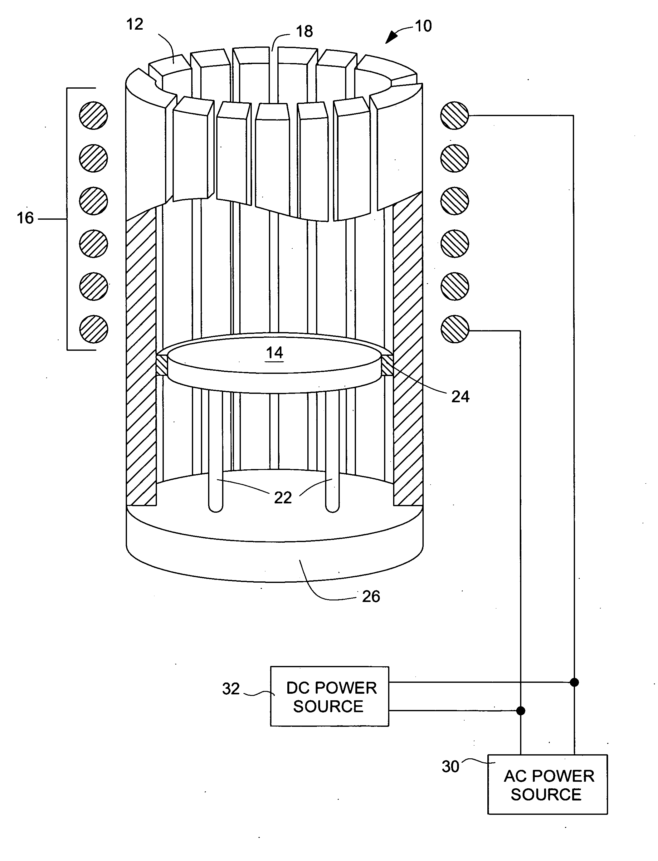
[0020] As used in this specification, the term “induced currents” generally refers to currents induced by an ac coil and the term “eddy currents” generally refers to currents generated by the movement of molten electrically conductive material across dc field lines. There is shown in FIG. 2, one example of a cold crucible induction furnace 10, with eddy current damping, of the present invention. For this example crucible 10 may comprise a cold crucible with wall 12 having slots 18, and base 14. The base may be separated from the wall by a layer of thermal and electrical insulation 24. The base may be raised above bottom structural support element 26 by suitable support means 22. Induction coil 16 is wound at least partially around the height of wall 12. Induction coil 16 is suitably connected to ac power source 30. AC current provided from the ac power source flows through coil 16 and establishes an ac field that penetrates into wall 12 and an electrically conductive material placed...


PUM

PropertyMeasurementUnit
chargeaaaaaaaaaa
widthaaaaaaaaaa
clarityaaaaaaaaaa

Abstract

Apparatus and method are provided for damping the induced fluid flow, particularly in the region of the base plate, in an electrically conductive material that is heated and melted in a cold crucible induction furnace. Damping is accomplished by establishing a dc magnetic field such that flow of the electrically conductive liquid metal in that dc magnetic field would induce eddy currents in the liquid metal which would generate forces that tend to oppose the flow. The dc magnetic field may be established by dc current flow in the ac induction coil that induces current in the material, dc current flow in a separate dc coil, or coils, constructed to prevent excessive induced losses, by discrete magnets, or a combination of any of the three prior methods. The dc magnetic field may also be established by dc current flow in one or more dc coils disposed around a magnetic pole piece located below the base of the furnace. One end of the magnetic pole piece is located adjacent to the bottom of the crucible base, so that the pole piece concentrates the dc field into the lower portion of the molten electrically conductive material.

Description

CROSS REFERENCE TO RELATED APPLICATIONS [0001] This application is a divisional of U.S. application Ser. No. 11 / 036,005, filed Jan. 14, 2005, which claims the benefit of U.S. Provisional Application No. 60 / 537,365, filed Jan. 17, 2004, both of which are hereby incorporated herein by reference in their entireties.FIELD OF THE INVENTION [0002] The present invention is in the technical field of melting electrically conductive materials, such as metals and alloys, by magnetic induction with a cold crucible induction furnace. BACKGROUND OF THE INVENTION [0003] A cold crucible induction furnace is used to melt and heat electrically conductive materials placed within the crucible by applying an alternating magnetic field to the materials. A common application of such furnace is the melting of a reactive metal or alloy, such as a titanium-based composition, in a controlled atmosphere or vacuum. FIG. 1(a) illustrates the principle features of a conventional cold crucible furnace. Referring t...

Claims


Application Information

Patent Timeline
Patent Type & Authority Applications(United States)
IPC IPC(8): H05B6/06F27D3/00H05B6/24
CPCF27B14/063F27B14/14F27D11/06H05B6/24
Inventor ROBERTS, RAYMONDKEOUGH, GRAHAM
Owner CONSARC
Why Eureka
Try Eureka