
Data transmission method and data transmission device

a data transmission and data technology, applied in the field of data transmission, can solve the problems of line immediately breaking down, inability to compensate for the state, and the failure rate of the entire system at least to increase the times of parallelism when compared with a single laser oscillator

Inactive Publication Date: 2007-06-28
HITACHI LTD
View PDF3 Cites 28 Cited by
  • Summary
  • Abstract
  • Description
  • Claims
  • Application Information

AI Technical Summary

Benefits of technology

[0013] Further more, the characteristics of this invention are furthered when an error correction occurs in the receiving equipment, the number of corrections is counted and BER of the link is calculated. Furthermore, a re

Problems solved by technology

Further, since a plurality of laser oscillators are mounted on a one module, and there are a plurality of optical link paths (frequency of parallelism), a failure rate of the entire system at least increases the times of the frequency of parallelism when compared with a single laser oscillator.
In the parallel transmission, there is a problem that when any one of a plurality of lines fails, the line immediately breaks down.
Moreover, there were problems that in the patent document 1, a method for transmitting a digital signal by serial method is disclosed, however, nothing is disclosed for the parallel method, and in the patent document 2, since the transmitted check data is employed for an error control (error correction), it is not possible to compensate for the state, where one channel is missing among a plurality of channels, which transmit information data.

Method used


Image

  • Data transmission method and data transmission device
  • Data transmission method and data transmission device
  • Data transmission method and data transmission device

Examples


Embodiment Construction

[0023] In the following, embodiments of this invention will be illustrated in detail based on drawings. However, this invention is not limited thereto.

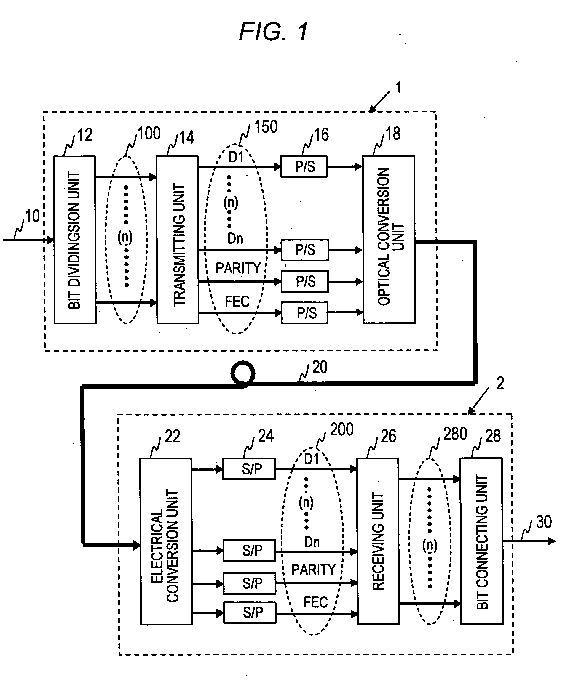
[0024]FIG. 1 is a block diagram illustrating the entire transmission system according to the embodiment of this invention.

[0025] The transmission system according to the embodiment of this invention is configured in such a way that the transmitting equipment 1 and the receiving equipment 2 are connected through the transmission line 20, and the transmitting equipment 1 transmits signal (data) through the transmission line 20, and the receiving equipment 2 receives it.

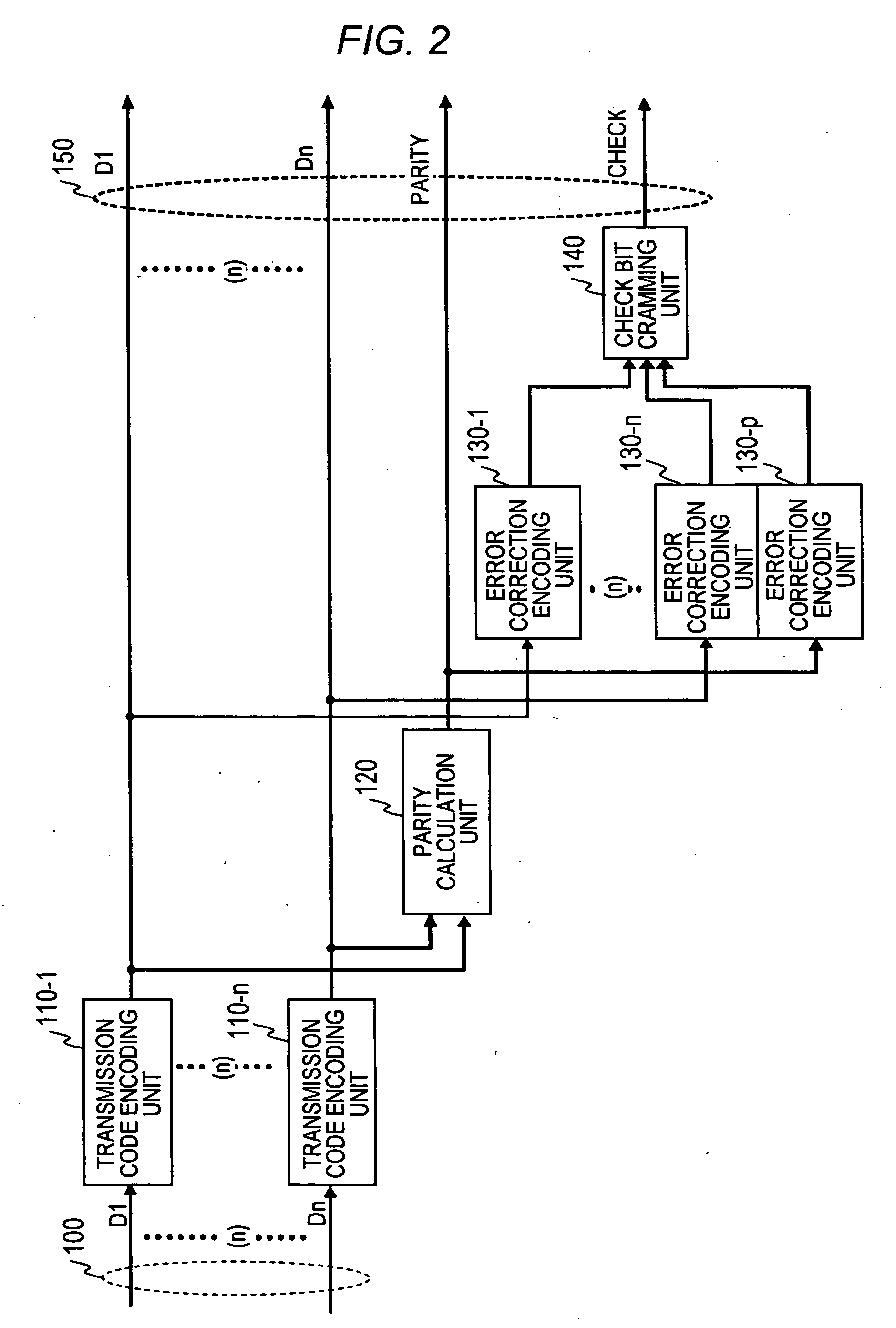
[0026] The transmitting equipment 1 is equipped with an input terminal 10, bit division unit 12, a plurality of data links 100, receiving unit 14, a plurality of links 150, a plurality of P / S conversion units 16, and optical conversion unit 18. The receiving equipment 2 is equipped with an electrical conversion unit 22, a plurality of S / P conversion units 24, a plurali...


PUM


Abstract

In a method for data transmission, which transmits data through a transmission line 20, which integrates a plurality of links into one transmission line, a first link group, which transmits information data by at least one link out of a plurality of links, a second link group, which transmits parity data generated by the information data by at least one link out of a plurality of links, which are different from the first link group, and a third link group, which generates an error check data related to an error correction from the information data or the parity data, when an error occurs in the information data or the parity data, and transmits by at least one link out of a plurality of links, which are different from the first link group and the second link group, are integrated and transmitted.

Description

TECHNICAL FIELD OF THE INVENTION [0001] This invention relates to a method for data transmission on a transmission line and communication equipment (transmitting equipment and receiving equipment) for the same application. BACKGROUND OF THE INVENTION [0002] Regarding a method for increasing the capacity of transmission on the data transmission channel for transmitting data, the number of links (namely, number of bits) for transmitting data has been increased and a parallel synchronization data transmission method has been employed, which can increase the capacity of transmission. In the parallel synchronous data transmission method, however, it is required that the timing of each link coincides in units of bits when data arrives at the receiving side. However, as the transmission distance increases, a difference in the transmission distance is created between links to cause to generate a transmission delay and to bring about a difference of arrival time (skew) between links. In orde...

Claims


Application Information

Patent Timeline
IPC IPC(8): H04J3/06H04B1/74H04B10/03H04B10/079H04B10/524H04J14/02H04L1/00H04L1/18H04L1/22
CPCH04J14/02H04J14/0226H04J14/0279H04L1/0057H04L2001/0096H04L1/0041
Inventor TOYODA, HIDEHIRO
Owner HITACHI LTD
Learn More