Liquid crystal display

a technology of liquid crystal display and display panel, which is applied in the field of liquid crystal display, can solve the problems of difficult to reduce power consumption, and sharp lowering of viewability, and achieve the effect of ensuring the luminance of transmission type display

Inactive Publication Date: 2007-06-28
JAPAN DISPLAY WEST
View PDF14 Cites 2 Cited by
  • Summary
  • Abstract
  • Description
  • Claims
  • Application Information

AI Technical Summary

Benefits of technology

[0015] A first object of the present invention is to provide a liquid crystal display compatible with high definition display, able to secure a luminance in transmission type display at an equivalent level as that of a display performing only transmission type display, and able to secure a required luminance in reflection type display.
[0016] A second object of the present invention is to provide a liquid crystal display compatible with high definition display, able to secure a luminance in transmission type display at an equivalent level as that of a display performing only transmission type display, and able to improve also the luminance of reflection type display.
[0036] According to the above invention, a focus portion is provided in the liquid crystal display panel, the display light used for the transmission type display is focused, and the luminance of the display light is increased. Due to this, even if the area of the transmission region is reduced, the luminance of the transmission type display can be sufficiently secured, so higher definition can be handled and the transmittance can be set low. Specifically, the transmittance is set as low as 4 percent.
[0038] Further, a low temperature polycrystalline silicon is used, the size of a thin film transistor TFT for every pixel is reduced, and the reflection region and the reflectance are improved. Further, a reflection film made of a metal having a high reflectance is formed, or a smooth reflection film is formed, and the reflection luminance is further improved.
[0039] Further, the color filter is provided in only the transmission region, color display having a high viewability is carried out for only the transmission type display, and the reflection type display is a black and white two color display sufficient for displaying characters. Due to this, there is no longer any reduction of the light due to the absorption at the color filter in the reflection region. Further, in the case of black and white display, pixels for displaying three colors of R, G, and B are all used for the black and white display, so the reflection luminance is further improved.

Problems solved by technology

In a transmission type liquid crystal display, the backlight accounts for 50 percent or more of the total power consumption, so it is difficult to reduce the power consumption.
Further, a transmission type liquid crystal display also has the problem that the display looks dark where the ambient light is bright, so the viewability is lowered.
On the other hand, in a reflection type liquid crystal display, a backlight is not provided, so there is no problem of an increase of the power consumption, but there is also a problem that the viewability is sharply lowered when the ambient light is low.
In a conventional dual reflection and transmission type liquid crystal display, however, though both transmission type display and reflection type display are provided, there were the problems that the luminance was insufficient and the viewability lower than the usual reflection type and the usual transmission type liquid crystal displays.
However, a reflection and transmission type display device stressing the reflection type is small in appeal to people's tastes, so in the actual market, liquid crystal displays employing transmission type display as a main display system are used more often for PDAs, mobile phones, laptop type personal computers, displays for car navigation, digital cameras, video cameras, etc.
Further, the minimum size of the window is not defined, therefore when transmission type display becomes the main display system, the reflection region cannot be reduced to the lowest limit.
Concerning increasing the definition to 200 ppi, due to the limits in design of liquid crystal pixels, for example the minimum width or pitch of signal lines and gate lines is not less than 5 μm, there are the disadvantages that the region which can be utilized for transmission type display for each pixel is reduced and the transmission type display luminance is reduced.
As explained above, however, this means the increase of the luminance of the backlight, so the power consumption of the liquid crystal display increases.
Therefore, this becomes a defect for a liquid crystal display boasting low power consumption.

Method used


Image

  • Liquid crystal display
  • Liquid crystal display
  • Liquid crystal display

Examples


first embodiment

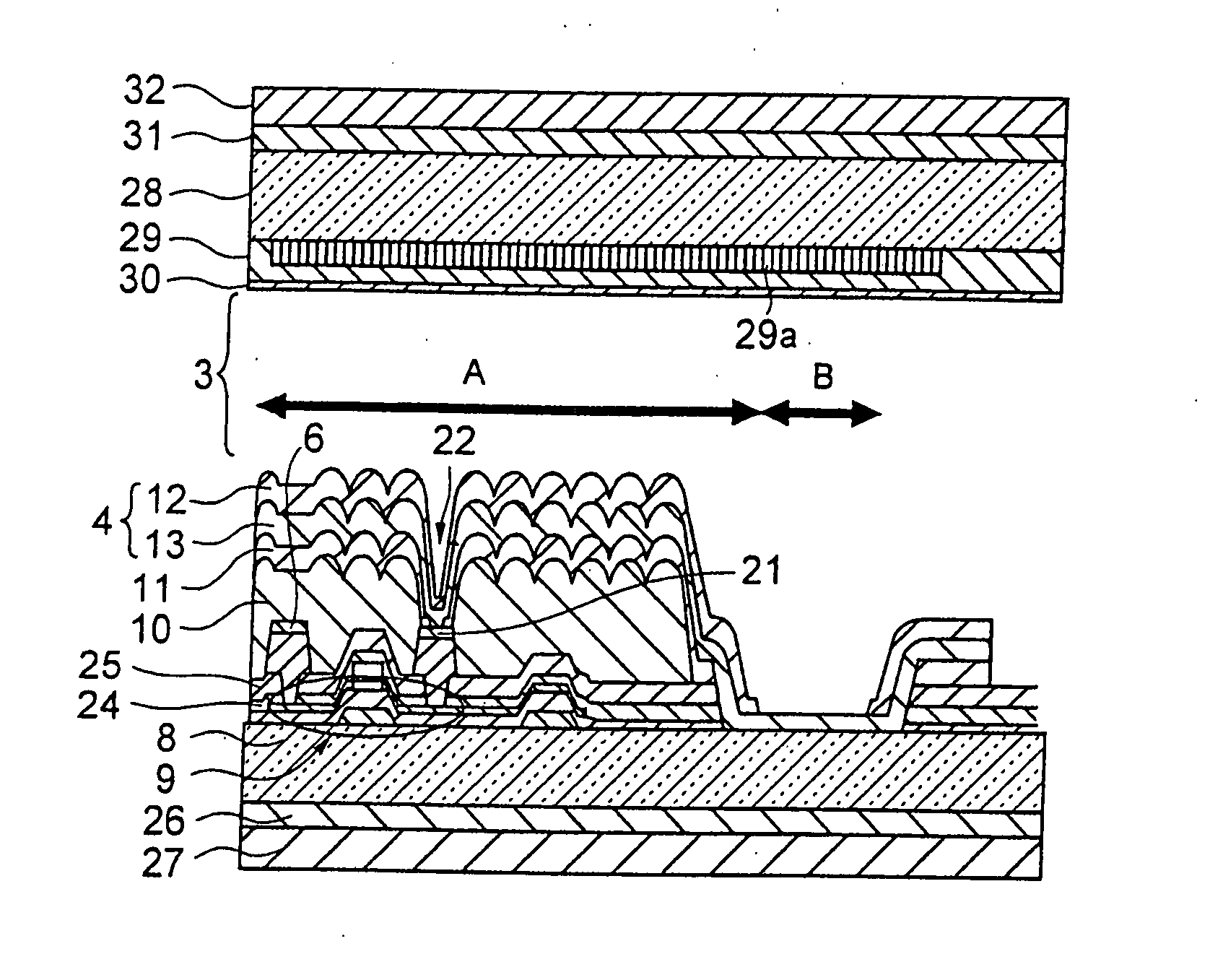
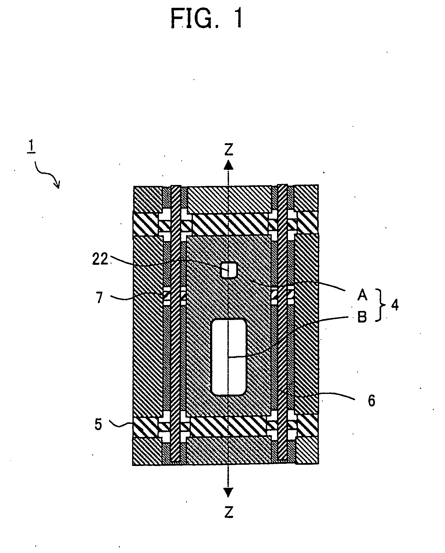
[0071]FIG. 1 is a plan view of one pixel's worth of a display panel 1 in the liquid crystal display of the present embodiment; and FIG. 2 shows the sectional structure of the display panel 1 along a Z-Z line in FIG. 1.

[0072] As shown in FIG. 2, the display panel 1 is constituted by a transparent insulating substrate 8 and a thin film transistor (TFT) 9 formed on that, a pixel region 4, etc., a transparent insulating substrate 28 arranged facing them and an overcoat layer 29 formed on that, a color filter 29a, and an counter electrode 30 and a liquid crystal layer 3 sandwiched between the pixel region 4 and the counter electrode 30.

[0073] The pixel regions 4 shown in FIG. 1 are arranged in a matrix. A gate line 5 for supplying a scan signal to the TFT 9 shown in FIG. 2 and a signal line 6 for supplying a display signal to the TFT 9 are provided around each pixel region 4 perpendicular to each other, whereby a pixel portion is constituted.

[0074] Further, on the transparent insulati...

second embodiment

[0133] Next, an explanation will be given of a second embodiment of the present invention in relation to FIG. 16 to FIG. 18.

[0134] The liquid crystal display of the present embodiment has a basic structure the same as that of the liquid crystal display explained in the first embodiment. Note, in the liquid crystal display of the present embodiment, the configuration of the color filter is different from that of the first embodiment.

[0135]FIG. 16 is a sectional view of the structure of a display panel 81 in the liquid crystal display of the present embodiment. The plan view of the display panel 81 shown in FIG. 16 is similar to that of FIG. 1. FIG. 16 is a sectional view at the center of this plan view.

[0136] Note that, in FIG. 16, the same notations are used for components similar to those of the liquid crystal display of the first embodiment, and overlapping explanations are omitted.

[0137] The structure of the display panel 81 shown in FIG. 16 is basically the same as that of t...

third embodiment

[0151] Next, an explanation will be given of a third embodiment of the present invention in relation to FIG. 19 to FIG. 21.

[0152] The liquid crystal display of the present embodiment has the same basic structure as that of the liquid crystal displays explained in the first and second embodiments. However, in the liquid crystal display of the present embodiment, the configuration of the reflection film is different.

[0153]FIG. 19 is a sectional view of the structure of a display panel 61 in the liquid crystal display of the present embodiment. The structure of the display panel shown in FIG. 19 is basically the same as that of FIG. 16. However, in the display panel 61 of FIG. 19, the surface of the reflection region A of the reflection electrode 62 is a smooth surface.

[0154] Note that, in FIG. 19 to FIG. 21, the same notations are attached to similar components to those of the liquid crystal displays of the first and second embodiments.

[0155] The surface of the reflection electrod...


PUM

PropertyMeasurementUnit
transmittanceaaaaaaaaaa

Abstract

A liquid crystal display able to deal with high definition display and able to secure both of a transmission type display luminance and a reflection type display luminance, wherein light from backlights 71a and 71b are focused by a lens sheet 74, luminance of the backlights is improved, a transmittance can be set at 4 percent to 10 percent, a reflectance can be set in a range from 1 percent to 25 percent, and high definition display is handled while securing a display light luminance equivalent to that of a liquid crystal display performing only transmission type display and a reflection display light luminance required for the display without increasing a power consumption of the backlights.

Description

TECHNICAL FIELD [0001] The present invention relates to a liquid crystal display, more particularly relates to a liquid crystal display using reflection type display and transmission type display together. BACKGROUND ART [0002] Liquid crystal displays are being used as displays of a broad spectrum of electronic apparatuses making use of their characteristics of being thin in shape and low in power consumption. For example, there are laptop type personal computers, displays for car navigation, personal digital assistants (PDAs), mobile phones, digital cameras, video cameras, and other electronic apparatuses using liquid crystal displays. Such liquid crystal displays include, roughly classified, transmission type liquid crystal displays controlling the passage and blocking of light from an internal light source referred to as a backlight by a liquid crystal panel to perform the display and reflection type displays for reflecting sunlight or other external light by a reflection plate o...

Claims


Application Information

Patent Timeline
Patent Type & Authority Applications(United States)
IPC IPC(8): G02F1/1335
CPCG02F1/133371G02F2203/02G02F1/133555G02F1/133514G02F1/1335
Inventor INO, MASUMITSU
Owner JAPAN DISPLAY WEST
Why Eureka
Try Eureka