
Actuator capable of reciprocal linear driving and rolling driving and power toothbrush using the same

a reciprocal linear and rolling technology, applied in the direction of carpet cleaners, cleaning machines, cleaning equipment, etc., can solve the problems of increasing the cost, complex configuration of the driving conversion mechanism for switching between reciprocal linear driving in the axial direction of the shaft and rolling driving around the axis, and the inability to perform the rolling driving of the shaft around the axis simultaneously while performing the reciprocal linear

Inactive Publication Date: 2007-06-28
MATSUSHITA ELECTRIC WORKS LTD
View PDF5 Cites 23 Cited by
  • Summary
  • Abstract
  • Description
  • Claims
  • Application Information

AI Technical Summary

Benefits of technology

[0007] The present invention is done to solve the problems of the above-mentioned conventional ones and purposed to provide an actuator capable of reciprocal linear driving and rolling driving of a shaft enabling low cost, miniaturization, weight saving and improvement of assemble workability, and to provide a power toothbrush using the same with low cost, miniaturization and weight saving.
[0013] According to such a configuration, the reciprocal linear driving unit and the rolling driving unit are provided on a single common shaft to adjoin in the axial direction thereof, so that reciprocal linear motion and rolling driving can be performed by the single shaft, simultaneously. Furthermore, the permanent magnets which constitute the reciprocal linear driving unit and the rolling driving unit are respectively provided on not the stator side but the moving object side, that is, around the axis of the shaft, so that the permanent magnets can be miniaturized and light-weighted respectively, in comparison with the case that the permanent magnets with larger diameter are provided on the stator side like the conventional one. Following to this, it is possible further to realize miniaturization, light-weighting and cost reduction of the actuator.
[0019] According to such a configuration, the brush body attached to the front end of the shaft can be driven in one of the mode for driving it reciprocally and linearly in the axial direction of the shaft, the mode for driving it rollingly around the axis, and the mode for driving it reciprocally and linearly in the axial direction of the shaft and rollingly around the axis simultaneously. Furthermore, the miniaturization, light-weighting and cost reduction of the actuator are possible as mentioned above, so that the miniaturization, light-weighting and cost reduction of the power toothbrush using the same can be realized, too.

Problems solved by technology

In such a power toothbrush utilizing the mechanical driving conversion mechanism, a configuration of the driving conversion mechanism for switching between the reciprocal linear driving in the axial direction of the shaft and the rolling driving around the axis becomes complex.
According to this, the power toothbrush becomes upsizing, and assembly of it becomes difficult causing the increase of the cost.
Furthermore, since the reciprocal linear driving in the axial direction and the rolling driving around the axis of the shaft are performed selectively by switching the rotation direction of the motor that is a single actuator, it is impossible to perform the rolling driving of the shaft around the axis simultaneously while performing the reciprocal linear driving in the axial direction.
This reciprocation type linear driving actuator can perform only the reciprocal linear driving of the shaft, but cannot perform the rolling driving.
Following to this, the cost of the permanent magnets 155 and 156 in material becomes expensive.
Furthermore, since the permanent magnets 155 and 156 are formed as the ring shape by combination of a plurality of arc-shaped permanent magnets, manufacturing process of the ring shaped permanent magnets 155 and 156 becomes complicated, and the cost of them in manufacturing becomes expensive.
As a result, the costs of the actuator using the conventional permanent magnets and coil and the power toothbrush using the same become expensive.

Method used


Image

  • Actuator capable of reciprocal linear driving and rolling driving and power toothbrush using the same
  • Actuator capable of reciprocal linear driving and rolling driving and power toothbrush using the same
  • Actuator capable of reciprocal linear driving and rolling driving and power toothbrush using the same

Examples


Embodiment Construction

[0035] An actuator capable of reciprocal linear driving and rolling driving and a power toothbrush using the same in accordance with an embodiment of the present invention is described in detail with reference to drawings.

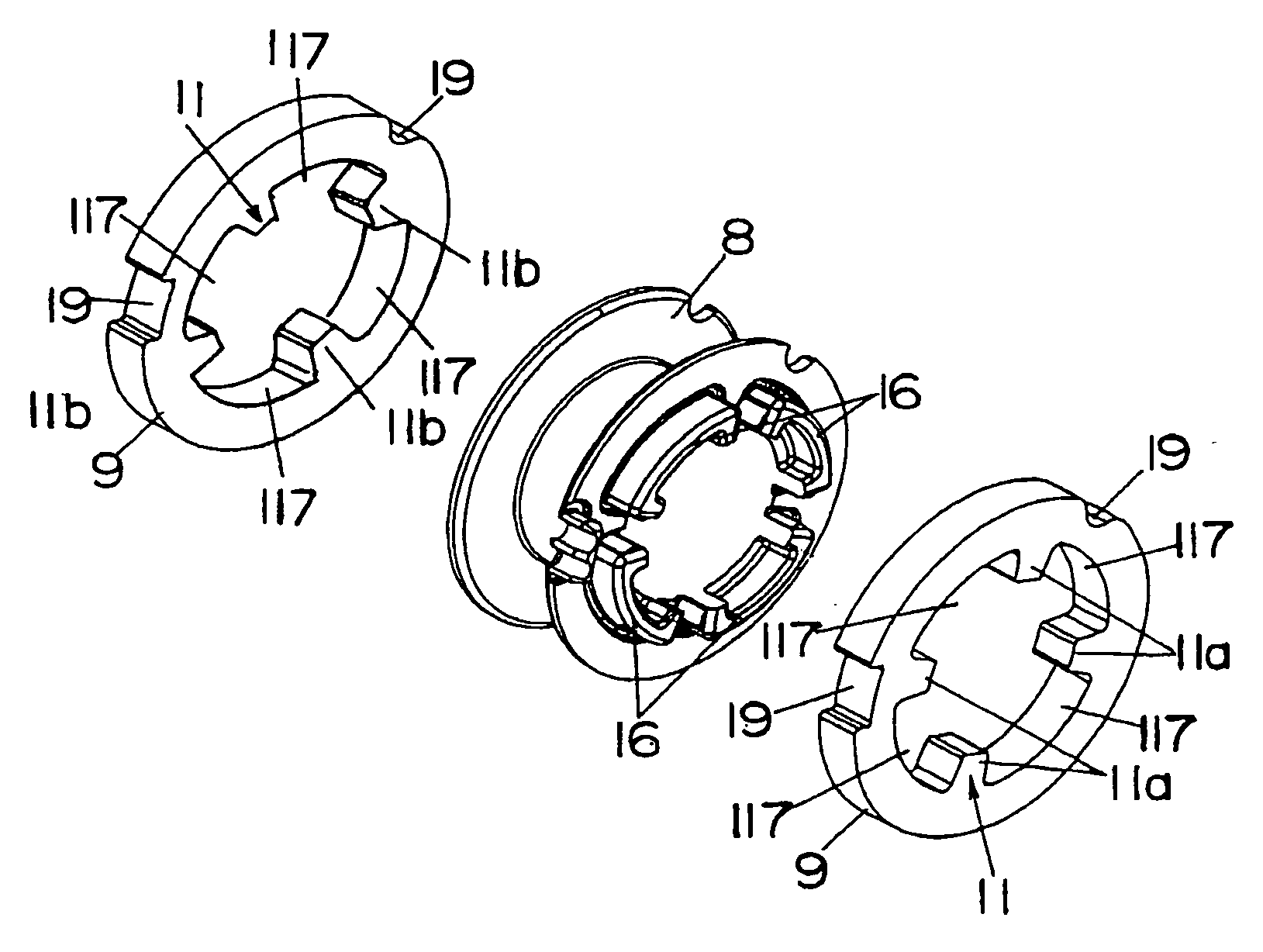
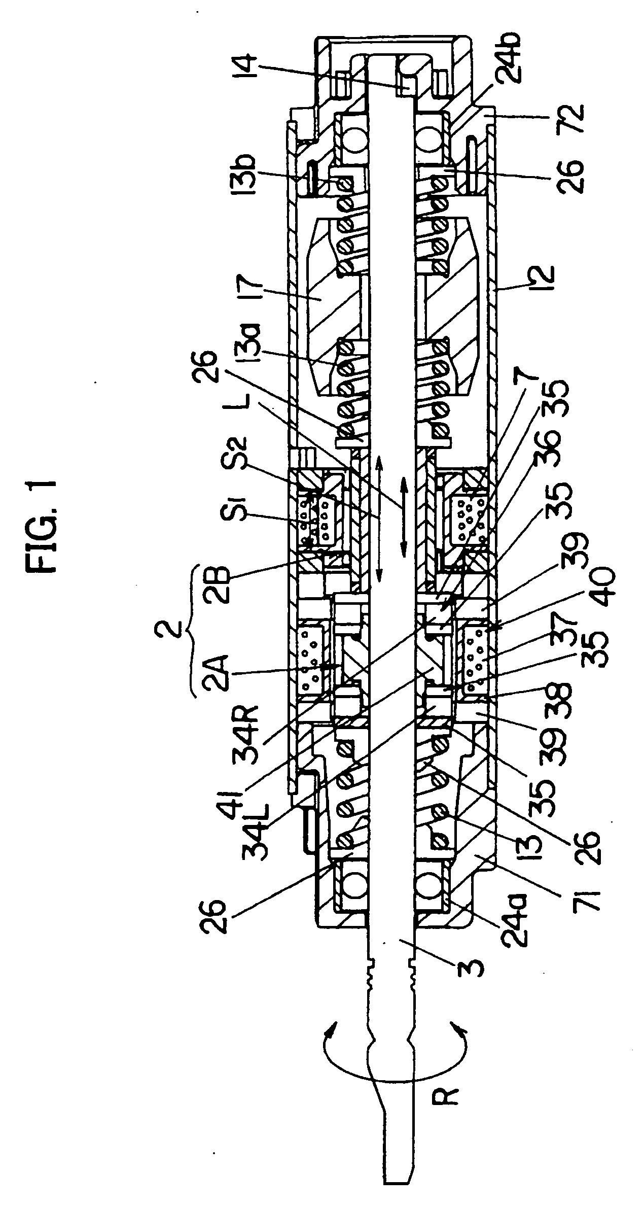
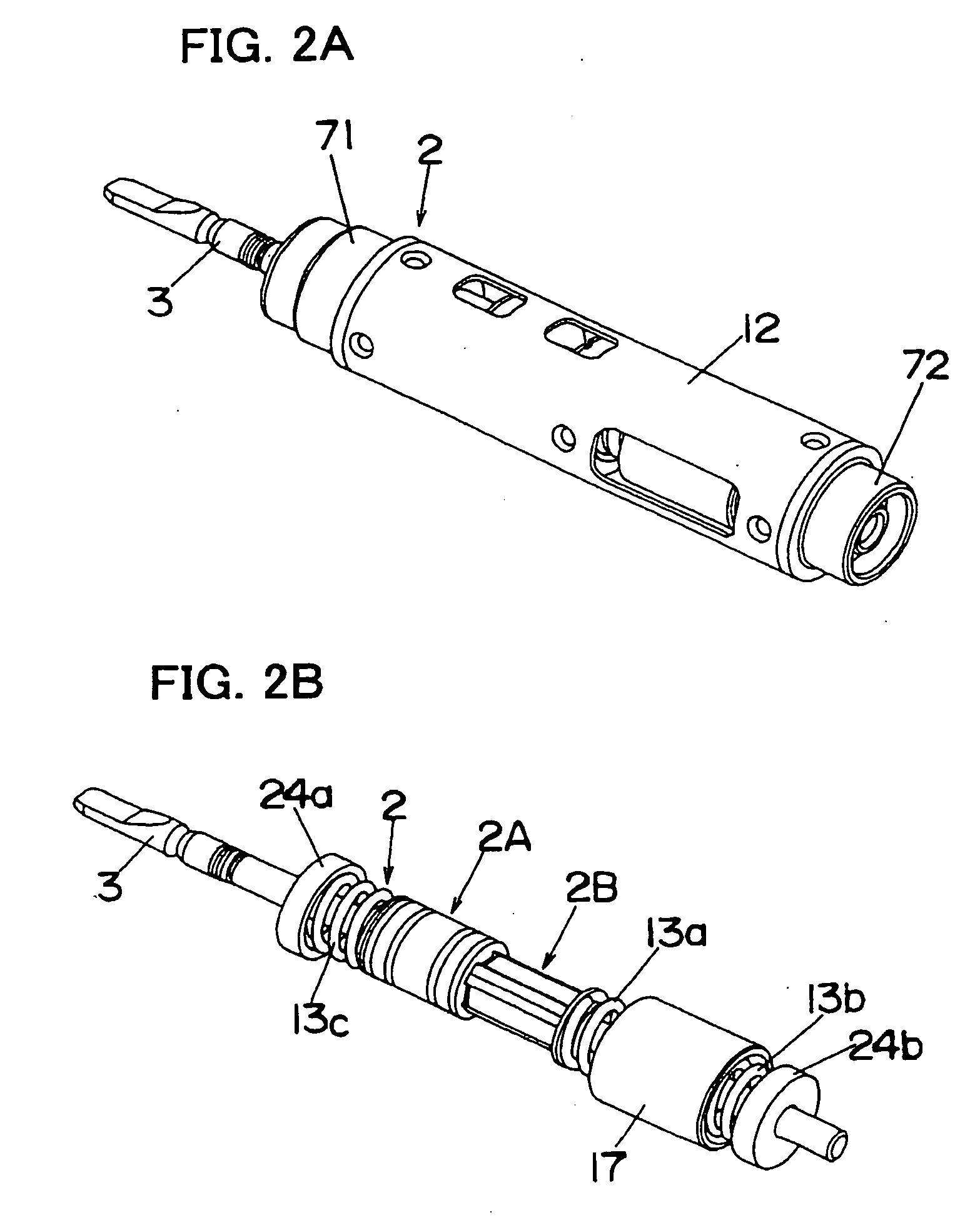
[0036] First, an actuator capable of reciprocal linear driving and rolling driving in accordance with this embodiment which is suitable for an actuator of a power toothbrush is described. FIG. 1 is a sectional side view showing a configuration of the actuator 2 capable of reciprocal linear driving and rolling driving in accordance with this embodiment. FIG. 2A is a perspective view showing an outer appearance configuration of the actuator 2. FIG. 2B is a perspective view showing an inner configuration in a state that a shielding case is detached. FIG. 3 is an exploded perspective view of the actuator 2. FIG. 4 is a view showing a structure for restricting rotation angle of a shaft provided at a rear end portion of the actuator 2.

[0037] The actuator 2 comprises a ...


PUM


Abstract

A reciprocal linear driving unit and a rolling driving unit are adjacently provided on a common single shaft in axial direction thereof, so that the reciprocal linear driving in the axial direction and the rolling driving around the axis are performed by the single shaft, simultaneously. Permanent magnets constituting the reciprocal linear driving unit and the rolling driving unit are respectively provided on moving object side instead of stator, in other words, they are provided around the axis of the shaft, thereby respective permanent magnets can be miniaturized and light-weighted. Following to this, miniaturization, light-weighting and cost reduction of an actuator and a power toothbrush using the same can be realized.

Description

TECHNICAL FIELD [0001] The present invention relates to an actuator capable of reciprocal linear driving of a drive shaft in axial direction thereof and capable of reciprocal rotation driving (rolling driving) around the axis in a predetermined region and a power toothbrush using the same. BACKGROUND ART [0002] As shown in, for example, Japanese Laid-Open Patent Application No. 9-173360, a power toothbrush, which can perform reciprocal linear driving in axial direction of a shaft and reciprocal rotation driving (rolling driving) around the axis selectively with using mechanical driving conversion mechanism, is known. In this power toothbrush, it is possible selectively to perform two motions of the reciprocal linear driving in the axial direction of the shaft and the rolling driving around the axis of the brush body attached to the shaft via the driving conversion mechanism by switching rotation direction of a motor. [0003] In such a power toothbrush utilizing the mechanical driving...

Claims


Application Information

Patent Timeline
IPC IPC(8): H02K35/00A46B13/00H02K33/00A61C17/22H02K7/02H02K33/06H02K33/16
CPCA61C17/3418A61C17/3445H02K33/06H02K33/16
Inventor SHIMIZU, HIROAKIMOTOHASHI, RYOYABUUCHI, HIDEKAZUNISHINAKA, TAKAHIROHIRATA, KATSUHIROHASEGAWA, YUYA
Owner MATSUSHITA ELECTRIC WORKS LTD
Learn More