
Method of manufacturing a matrix body drill bit

a technology of matrix body and drill bit, which is applied in the field of improved method of manufacturing earthboring bits, can solve the problems of reducing the life of the bit, difficult to identify the internal hydraulic passageways of a particular bit, and the inability of designers to effectively analyze the hand-shaped internal hydraulic passageways of the bit for improvement, etc., and achieves the effect of reducing fluid separation

Inactive Publication Date: 2007-06-21
SMITH INT INC
View PDF68 Cites 2 Cited by
  • Summary
  • Abstract
  • Description
  • Claims
  • Application Information

AI Technical Summary

Benefits of technology

[0016] In another aspect, the present invention relates to a method of manufacturing an earth-boring bit having a fluid plenum and at least one fluid pathway. The method includes constructing a computer model of the flow characteristics through the fluid plenum and the at least one fluid pathway of the earth-boring bit, and determining a geometry to reduce fluid separation through the at least one fluid pathway. The method further includes constructing a plenum blank based upon the computer model, and sintering matrix powder between the plenum blank and a bit head mold to create the fluid plenum and at least one fluid pathway.

Problems solved by technology

The hand shaping of plenum blanks in manufacturing matrix bit bodies creates several issues.
An internal plenum design for one particular bit may work well, where the same design for another bit may encounter problems that lead to a washout from internal erosion or to a reduced bit life.
Furthermore, the process of hand shaping the plenum blanks makes it difficult to identify problems with the internal hydraulic passageways of a particular bit.
Designers cannot effectively analyze hand-shaped internal hydraulic passageways of the bit for improvement.
As such, the internal plenum and transition areas to the nozzle ports cannot be reconstructed into a computer model for analysis.
Therefore, plenum blanks with optimized transitions from the internal plenum to the nozzle ports are difficult to create.
Such ineffective designs can easily occur if sufficient care is not taken by the worker to hand shape the transition region of the plenum blank properly.
In a market that is driven by using a drill bit multiple times, internal erosion can limit revenue by reducing the number of times a drill bit can be used and rebuilt.
While PDC cutters can be replaced several times on a drill bit, the internal hydraulic passageways of a drill bit made from matrix powder are difficult to rebuild or replace.

Method used


Image

  • Method of manufacturing a matrix body drill bit
  • Method of manufacturing a matrix body drill bit
  • Method of manufacturing a matrix body drill bit

Examples


Embodiment Construction

[0033] Referring now to FIG. 3, a bit head mold 401 formed in the shape of the external geometry of a matrix body bit is shown. The external geometry of bit head mold 401 includes junk slot geometry 403 and blade geometry 405. Cutter plugs 407 are positioned and glued in blade geometry 405 to create receptacles for later installation of PDC cutters. Furthermore, bit head mold 401 includes features to receive nozzle displacements 409. Nozzle displacements 409 define the necessary internal workings of a matrix body bit and may include seal glands, threads, sockets, or any other features used to seal and secure fluid nozzles in place. Alternatively, nozzle displacements 409 may only create space for a port to allow drilling fluid flow without any addition of a fluid nozzle. Preferably, nozzle displacements 409 are manufactured from graphite or cast sand such that the geometries of the internal hydraulic passageways created thereby are not distorted in the sintering process. After nozzl...


PUM

PropertyMeasurementUnit
computational fluid dynamicsaaaaaaaaaa
nozzle displacementaaaaaaaaaa
wear resistantaaaaaaaaaa

Abstract

A method of manufacturing an earth-boring bit having a fluid plenum and a plurality of fluid pathways includes modeling flow characteristics of the fluid plenum and the plurality of fluid pathways, optimizing the flow characteristics to minimize fluid separation through each fluid pathway, constructing a plenum blank from the optimized model, and sintering matrix power between the plenum blank and a bit head mold to create the fluid plenum and plurality of fluid pathways.

Description

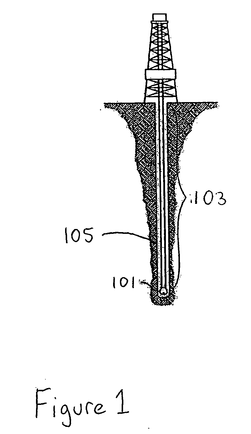
BACKGROUND OF INVENTION [0001] 1. Field of the Invention [0002] The present invention relates to drill bits used in the oil and gas industry. Specifically, the invention relates to an improved method of manufacturing earth-boring bits for drilling earth formations. [0003] 2. Background Art [0004] Drill bits are used in the oil and gas industry to drill earth formations in the exploration for gas and oil. FIG. 1 shows a drilling rig which incorporates a drill bit 101. Drill bit 101 is connected to the bottom of a drill string 103 to drill a wellbore 105. The drill string is controlled by surface equipment configured to rotate the drill string, apply downward force to the drill bit to penetrate the earth formation (referred to as weight on bit (“WOB”)), and supply drilling fluid to drill bit 101 by pumping the fluid through a bore of the drill string. Because a variety of earth formations are penetrated in the pursuit of oil and gas, several different types and configurations of drill...

Claims


Application Information

Patent Timeline
Patent Type & Authority Applications(United States)
IPC IPC(8): G06G7/48
CPCE21B10/60B22F5/10E21B10/602
Inventor ROBERTS, TIMOTHY SCOTTLARSEN, JAMES LAYNETERRACINA, DWAYNE P.
Owner SMITH INT INC
Learn More