Stator and torque converter containing the same
- Summary
- Abstract
- Description
- Claims
- Application Information
AI Technical Summary
Benefits of technology
Problems solved by technology
Method used
Image
Examples
Embodiment Construction
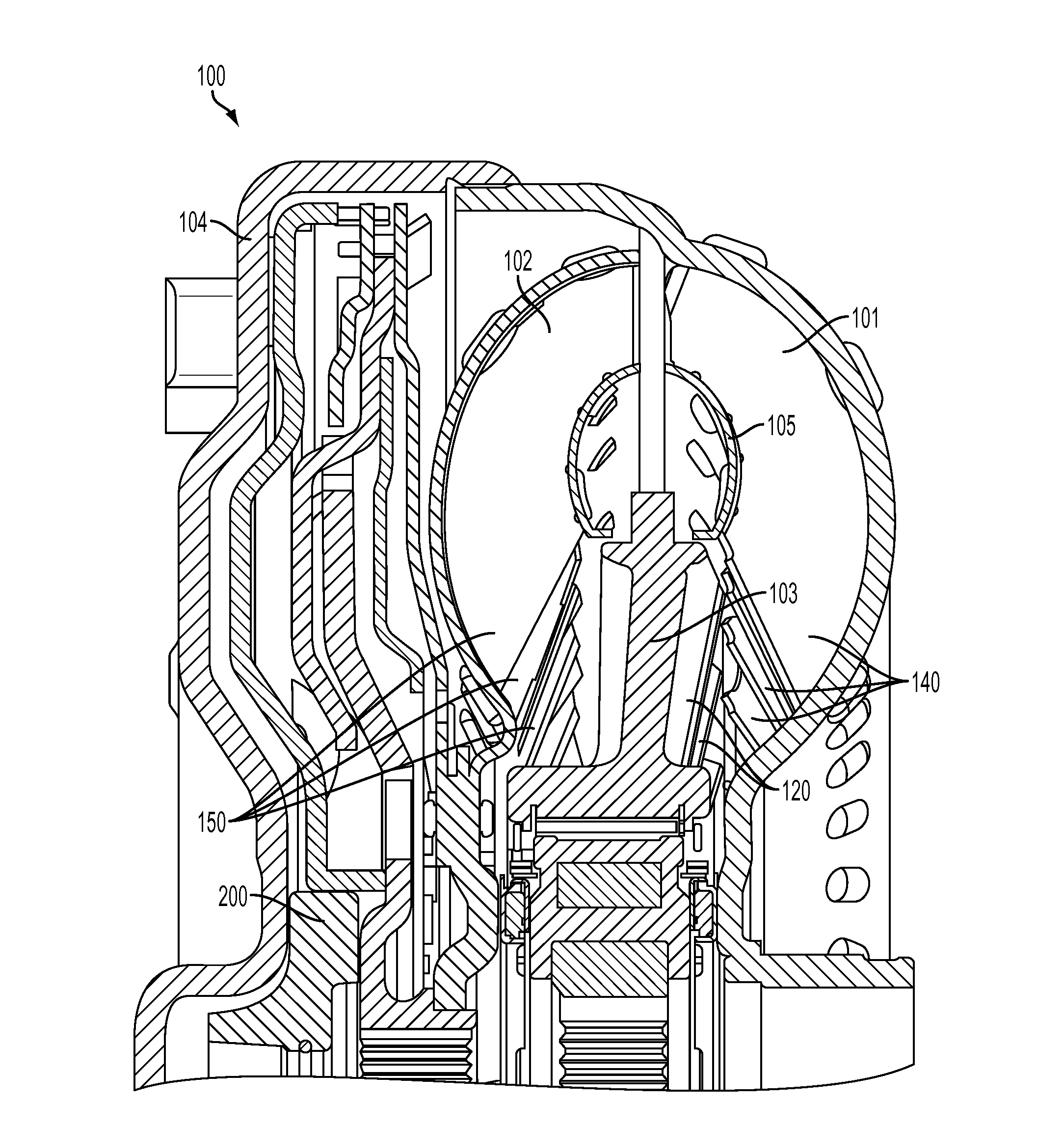
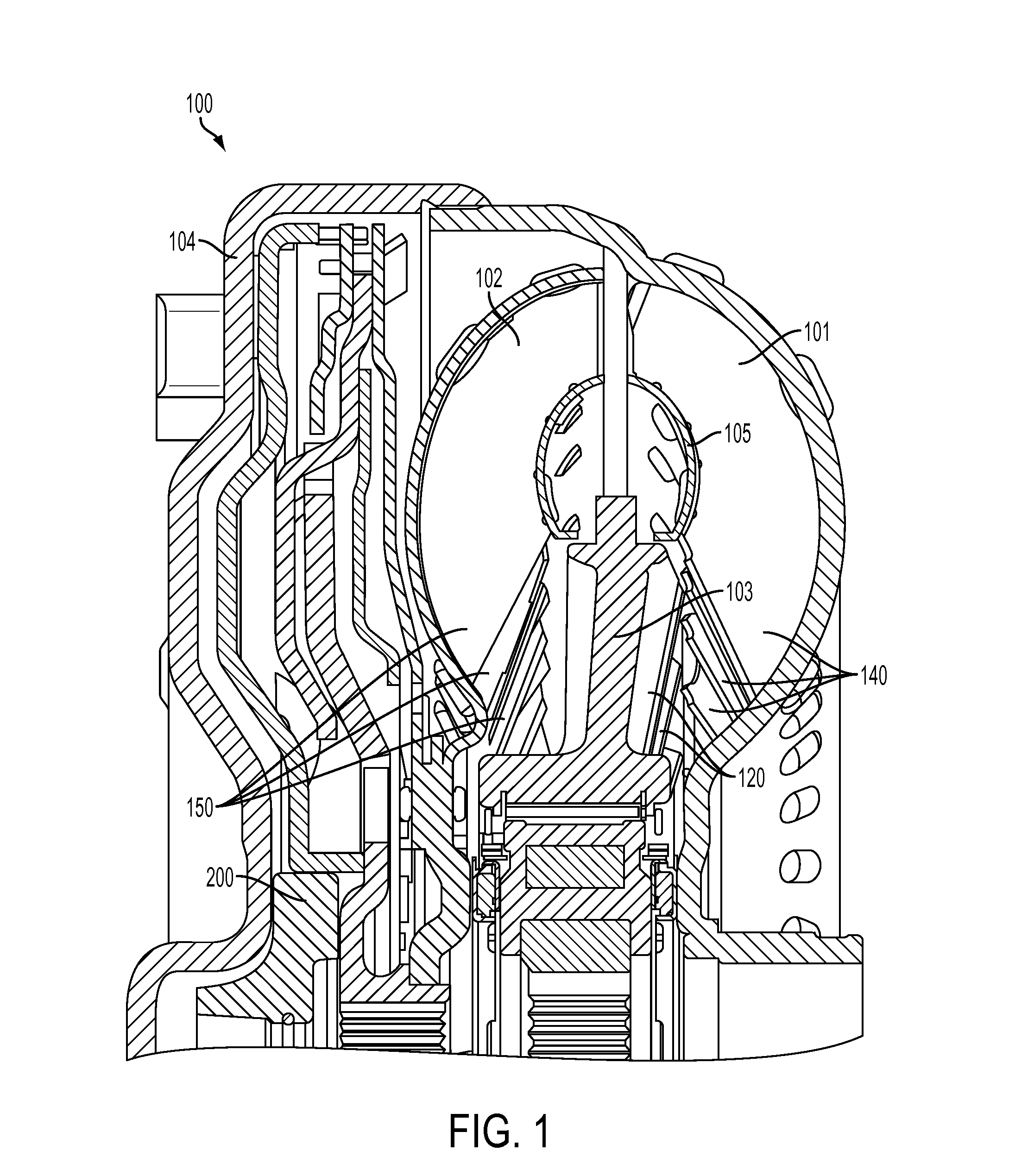
[0029]FIG. 1 is a cross sectional view of a torque converter 100 showing the location of an impeller 101, turbine 102, stator 103, cover 104, torus ring, 105, and thrust washer 200. During operation of the torque converter 100, torque generated from the engine (not shown) drives the impeller 101. The cover 104 is attached to the impeller 101, so both the cover 104 and the impeller 101 rotate at the same speed as the engine. The turbine 102 has a plurality of turbine blades 150 and the impeller 101 has a plurality of impeller blades 140 oriented so that as the impeller 101 rotates, the fluid within the impeller 101 is forced out of the impeller 101 into the turbine 102, transmitting energy to the turbine 102 and forcing it to rotate. The stator103 has a plurality of stator blades 120 oriented to direct the fluid leaving the turbine 102 into the impeller 101 in the rotational direction of the impeller 101 rather than in a direction opposing the impeller's rotation.
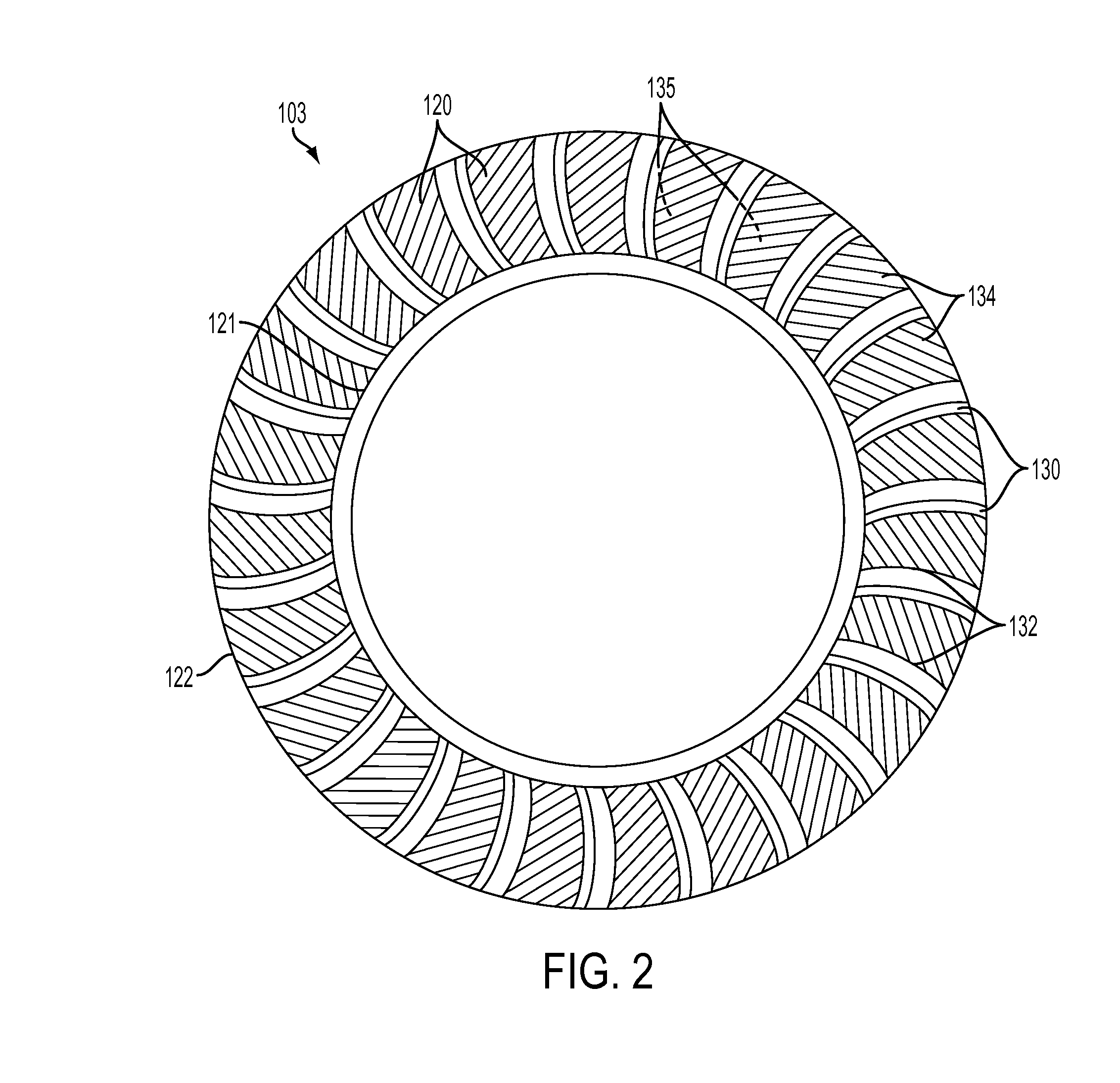
[0030]FIGS. 2 and 3 ...
PUM
 Abstract
Description
Claims
Application Information
 - R&D
- Intellectual Property
- Life Sciences
- Materials
- Tech Scout
- Unparalleled Data Quality
- Higher Quality Content
- 60% Fewer Hallucinations
Browse by: Latest US Patents, China's latest patents, Technical Efficacy Thesaurus, Application Domain, Technology Topic, Popular Technical Reports.
© 2025 PatSnap. All rights reserved.Legal|Privacy policy|Modern Slavery Act Transparency Statement|Sitemap|About US| Contact US: help@patsnap.com


