
Diffuser bump vane profile

Active Publication Date: 2012-11-15
BAKER HUGHES INC
View PDF5 Cites 5 Cited by
  • Summary
  • Abstract
  • Description
  • Claims
  • Application Information

AI Technical Summary

Benefits of technology

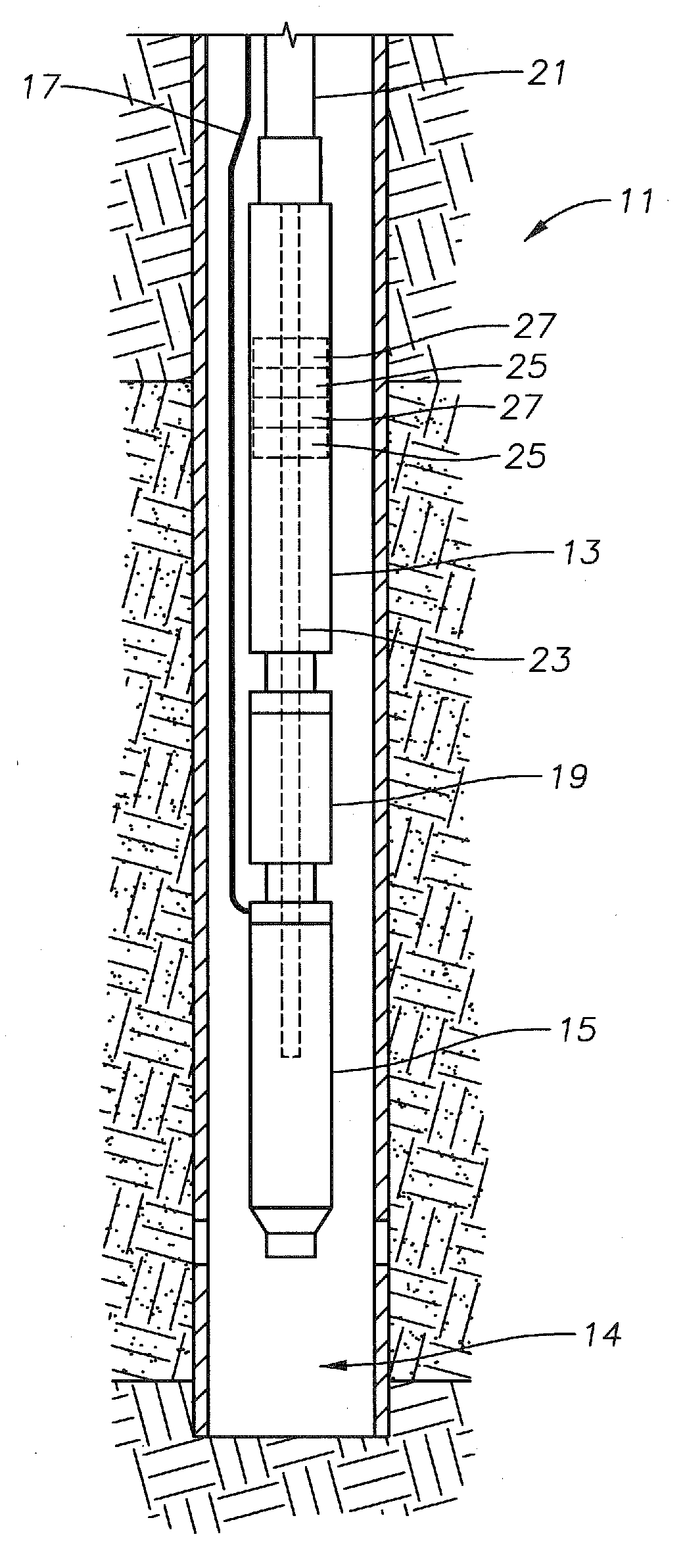
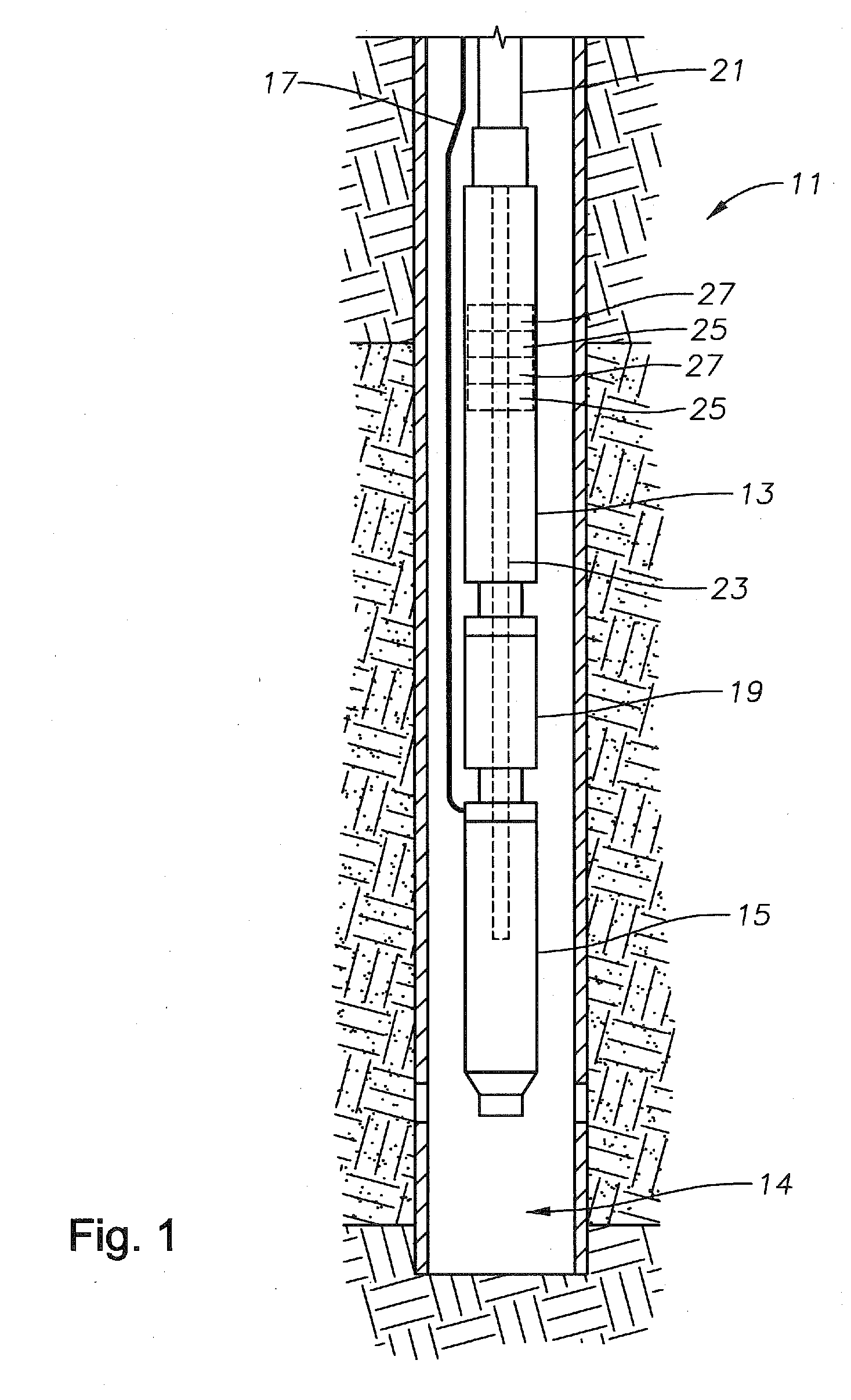
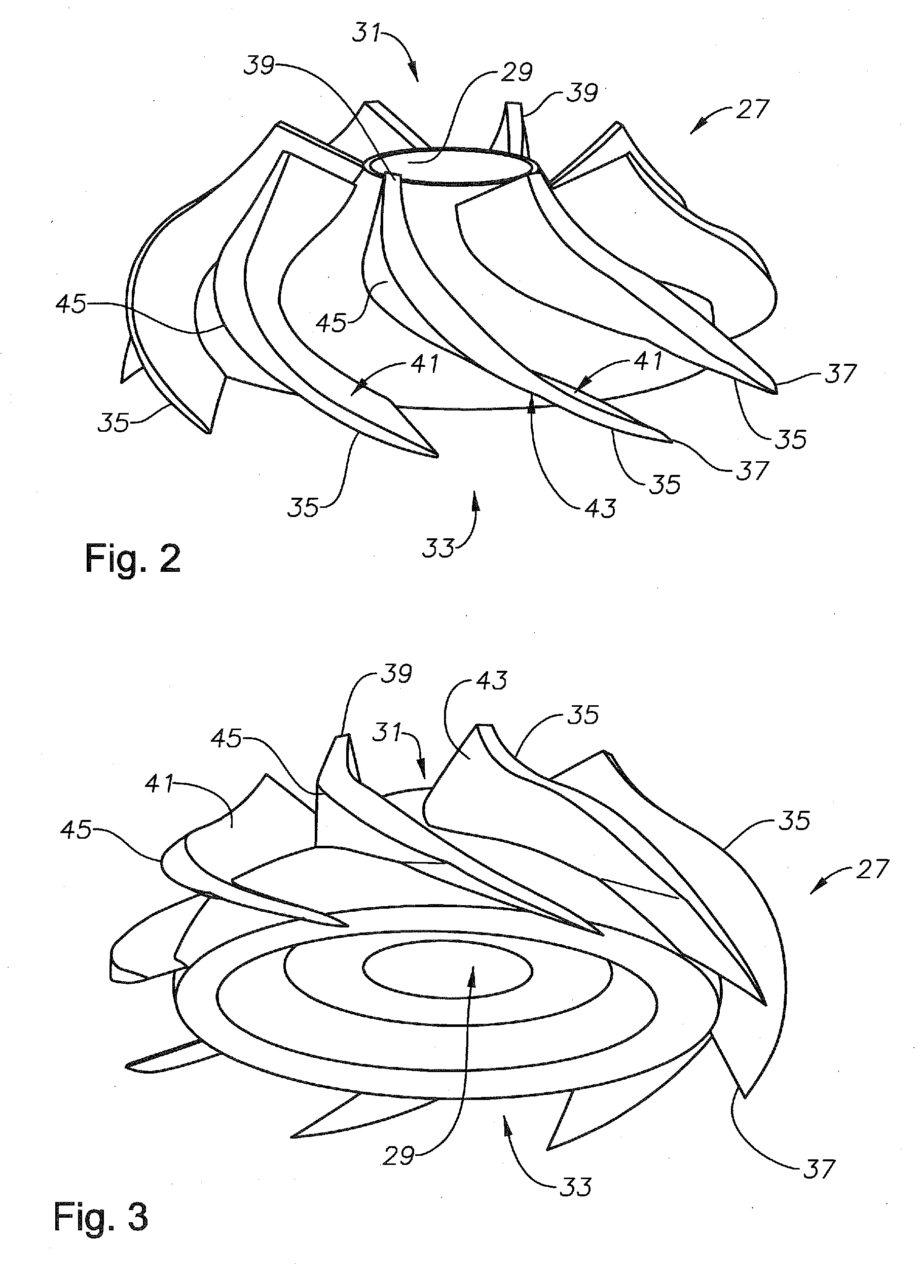
[0007]These and other problems are generally solved or circumvented, and technical advantages are generally achieved, by preferred embodiments of the present invention that provide a diffuser of an electric submersible pump having a bump formed thereon and a method to increase pump efficiency and head.
[0010]In accordance with yet another embodiment of the present invention, a method for increasing pump efficiency and pumping head of an electric submersible pumping (ESP) system is disclosed. The method provides an ESP having a pump portion and a motor portion and positions an impeller in the pump portion for moving fluid, the impeller keyed to a rotating shaft in the pump portion. The method also positions a diffuser downstream of the impeller so that the diffuser will direct moving fluid discharged from the impeller toward the rotating shaft in the pump portion. The method mechanically couples the motor portion to the pump portion so that the motor portion may variably rotate the impeller in the pump. Rotation of the impeller accelerates fluid from an area proximate to the rotating shaft and discharges the fluid proximate to a leading edge of a vane of the diffuser. The method forms the diffuser so that the vane of the diffuser has a low pressure surface with a length greater than the length of a high pressure surface of the vane, the high pressure surface opposite the low pressure surface.
[0011]The disclosed embodiments provide an ESP with decreased separation of fluid from the vanes of the diffuser. Inclusion of a bump in the diffuser vane increases the length of the vane without increasing the axial length of the diffuser. This causes a decrease in fluid turbidity as the fluid flows through the diffuser and into the downstream impeller. As a result, pump efficiency and pumping head increase. In addition, the disclosed embodiments provide an ESP with decreased separation of fluid from the blades of the impeller. Again, this causes a decrease in fluid turbidity as it flows from the impeller into the downstream diffuser. As a result, pump efficiency and pumping head increase.

Problems solved by technology

As the fluid moves along the low pressure side, it may separate from the low pressure surface causing the flow to be turbulent.
Turbulent flow decreases the ability of the impeller in the next pump stage to accelerate the fluid, thereby decreasing pump efficiency and the overall pump head.
However, in modern pumps in oil and gas environments, there may be insufficient space to include long diffusers in ESPs.

Method used


Image

  • Diffuser bump vane profile
  • Diffuser bump vane profile
  • Diffuser bump vane profile

Examples


Embodiment Construction

[0019]The present invention will now be described more fully hereinafter with reference to the accompanying drawings which illustrate embodiments of the invention. This invention may, however, be embodied in many different forms and should not be construed as limited to the illustrated embodiments set forth herein. Rather, these embodiments are provided so that this disclosure will be thorough and complete, and will fully convey the scope of the invention to those skilled in the art. Like numbers refer to like elements throughout, and the prime notation, if used, indicates similar elements in alternative embodiments.

[0020]In the following discussion, numerous specific details are set forth to provide a thorough understanding of the present invention. However, it will be obvious to those skilled in the art that the present invention may be practiced without such specific details. Additionally, for the most part, details concerning electric submersible pump operation, construction, us...


PUM


Abstract

An electric submersible pump (ESP) assembly increases pump efficiency and pump head with a diffuser that includes a diffuser vane having a low pressure surface with a length greater than a length of a high pressure surface of the vane. The diffuser vane includes a leading edge at a downstream end of the vane and a trailing edge at an upstream end of the vane. The curved high pressure surface extends between the leading edge and the trailing edge. The curved low pressure surface extends between the leading edge and the trailing edge opposite the high pressure surface. The low pressure surface has a bump formed thereon to increase the length of the low pressure surface so that fluid flowing along the low pressure surface is substantially laminar, thereby increasing pump efficiency and pump head.

Description

[0001]This application claims priority to and the benefit of co-pending U.S. Provisional Application No. 61 / 485,952, by Song, filed on May 13, 2011, entitled “Diffuser Bump Vane Profile,” which application is incorporated herein by reference.FIELD OF THE INVENTION[0002]This invention relates in general to pumps and, in particular, to a pump diffuser for a more laminar fluid flow profile through the diffuser during operation of the ESP.BRIEF DESCRIPTION OF RELATED ART[0003]Wells may use an artificial lift system, such as an electric submersible pump (ESP) to lift well fluids to the surface. Where ESPs are used, the ESP may be deployed by connecting the ESP to a downhole end of a tubing string and then run into the well on the end of the tubing string. The ESP may be connected to the tubing string by any suitable manner. In some examples, the ESP connects to the tubing string with a threaded connection so that an uphole end or discharge of the ESP threads onto the downhole end of the ...

Claims


Application Information

Patent Timeline
IPC IPC(8): F04D13/08
CPCF04D13/10F04D29/548F04D29/448E21B43/128
Inventor SONG, BAOJUN
Owner BAKER HUGHES INC
Learn More