
Sensorless relative humidity control in a fuel cell application

a technology of relative humidity control and fuel cell, which is applied in the direction of cell components, process and machine control, instruments, etc., can solve the problems of inability to accurately determine the relative humidity of the cathode input airflow, the inability of dew-point sensors to provide the required accuracy is not standard in automotive applications, and the cost of sensors is relatively high

Inactive Publication Date: 2007-06-21
GM GLOBAL TECH OPERATIONS LLC
View PDF8 Cites 27 Cited by
  • Summary
  • Abstract
  • Description
  • Claims
  • Application Information

AI Technical Summary

Benefits of technology

The present invention provides a way to determine the humidity of air that enters a fuel cell without using a special sensor. This is done by using a water vapor transfer unit that adds water to the air. An algorithm is used to determine the amount of water that flows into the fuel cell, which is then used to calculate the humidity of the air. This technique simplifies the process of measuring the humidity of the air and makes it more cost-effective.

Problems solved by technology

The technical problem addressed in this patent text is the need for a more accurate and reliable method for determining the relative humidity of the cathode input airflow in a fuel cell system, without the need for an expensive and unreliable dew-point sensor.

Method used


Image

  • Sensorless relative humidity control in a fuel cell application
  • Sensorless relative humidity control in a fuel cell application
  • Sensorless relative humidity control in a fuel cell application

Examples


Embodiment Construction

[0017] The following discussion of the embodiments of the invention directed to a technique for modeling a water vapor trap unit in a fuel cell system to determine the relative humidity of a cathode input airflow is merely exemplary in nature, and is in no way intended to limit the invention or its applications or uses.

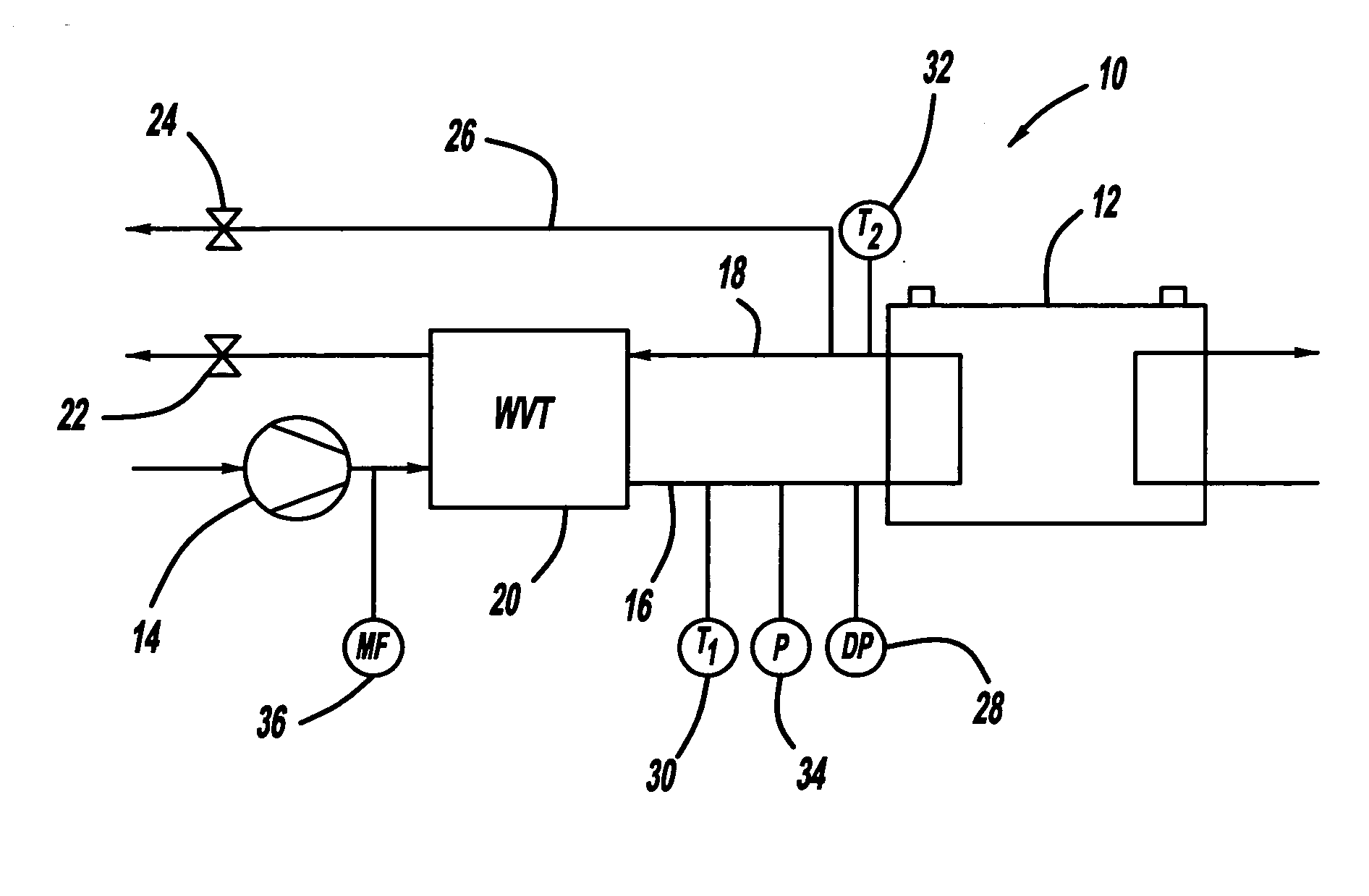
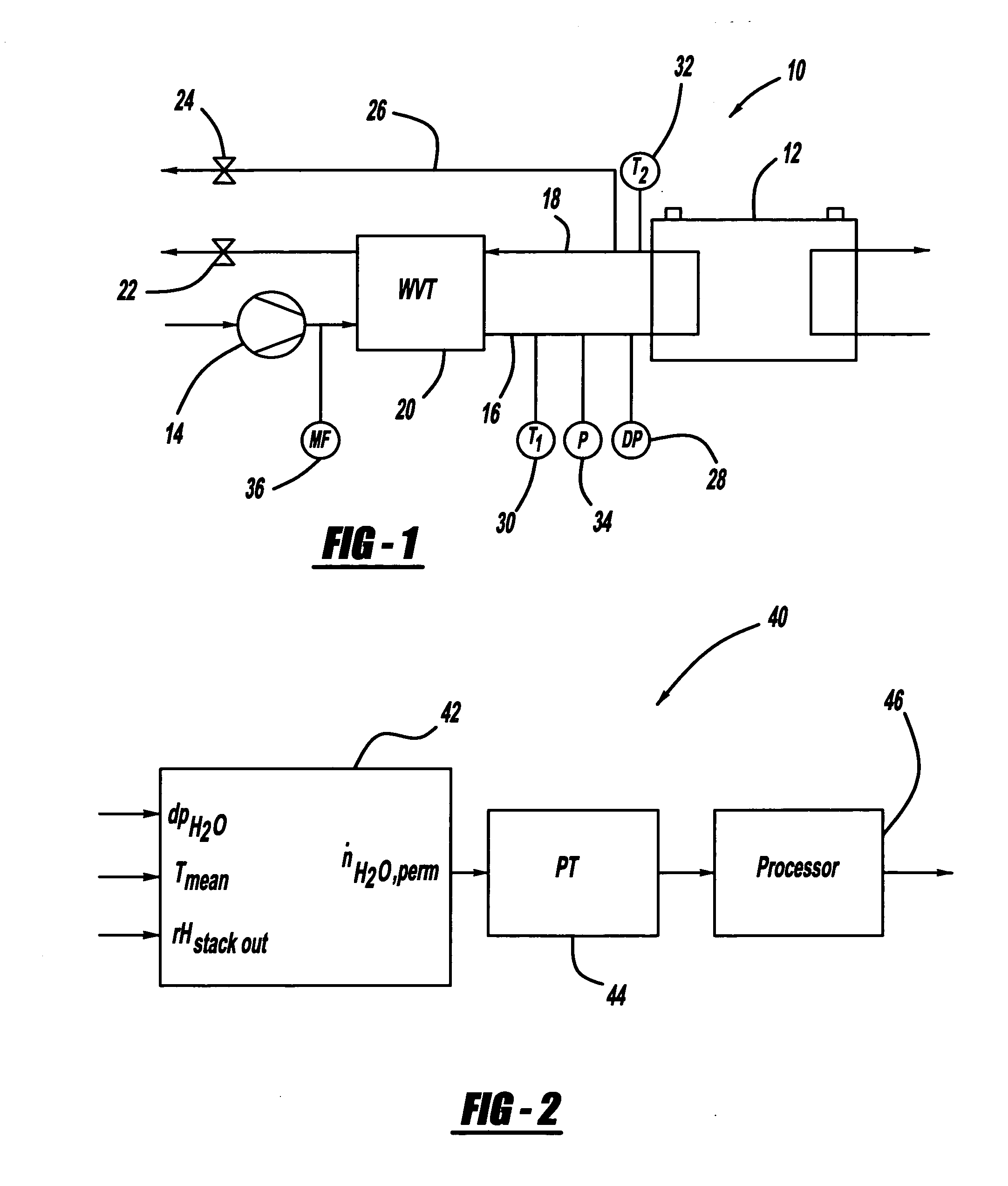
[0018] According to the present invention, a method for estimating the transferred flow of the water through the WVT unit 20 is disclosed that can be used to determine the relative humidity of the cathode input airflow to the stack 12 on the line 16. From the transferred water flow estimation, the temperature of the airflow, the pressure in the input line 16 and the position of the control valves 22 and 24, the relative humidity of the cathode input airflow can be calculated. By adding the product water mass flow to the cathode airflow, the estimation of the stack outlet relative humidity can be determined by knowing the temperature and pressure. The flow distributio...


PUM


Abstract

A technique for determining the relative humidity of the cathode input airflow to a fuel cell stack that eliminates the need for a dew-point sensor. The cathode input airflow is humidified by a water vapor transfer unit that uses water in the cathode exhaust gas. The technique employs an algorithm that determines the flow of water into the cathode inlet of the stack. In one embodiment, the algorithm determines the volume flow of water through the water vapor transfer unit using the Arrhenius equation, and then converts the water volume flow to a water mole flow. The algorithm then uses the water mole flow through the water vapor transfer unit and the water mole flow of ambient air to determine the water mole flow into the cathode inlet. The algorithm then uses the water mole flow into the cathode inlet to determine the relative humidity of the cathode airflow.

Description


Claims


Application Information

Patent Timeline
Owner GM GLOBAL TECH OPERATIONS LLC
Learn More