Two camera stereoscopic 3D rig improvements

a stereoscopic 3d and camera technology, applied in stereoscopic photography, instruments, optics, etc., can solve problems such as inability to allow close-up shooting

Inactive Publication Date: 2007-06-21
3ALITY DIGITAL SYST
View PDF2 Cites 19 Cited by
  • Summary
  • Abstract
  • Description
  • Claims
  • Application Information

AI Technical Summary

Problems solved by technology

This configuration does not allow close-up shooting because of this limitation.

Method used


Image

  • Two camera stereoscopic 3D rig improvements
  • Two camera stereoscopic 3D rig improvements
  • Two camera stereoscopic 3D rig improvements

Examples


Embodiment Construction

[0021] a) Trapezoidal Beam-splitter Mirror.

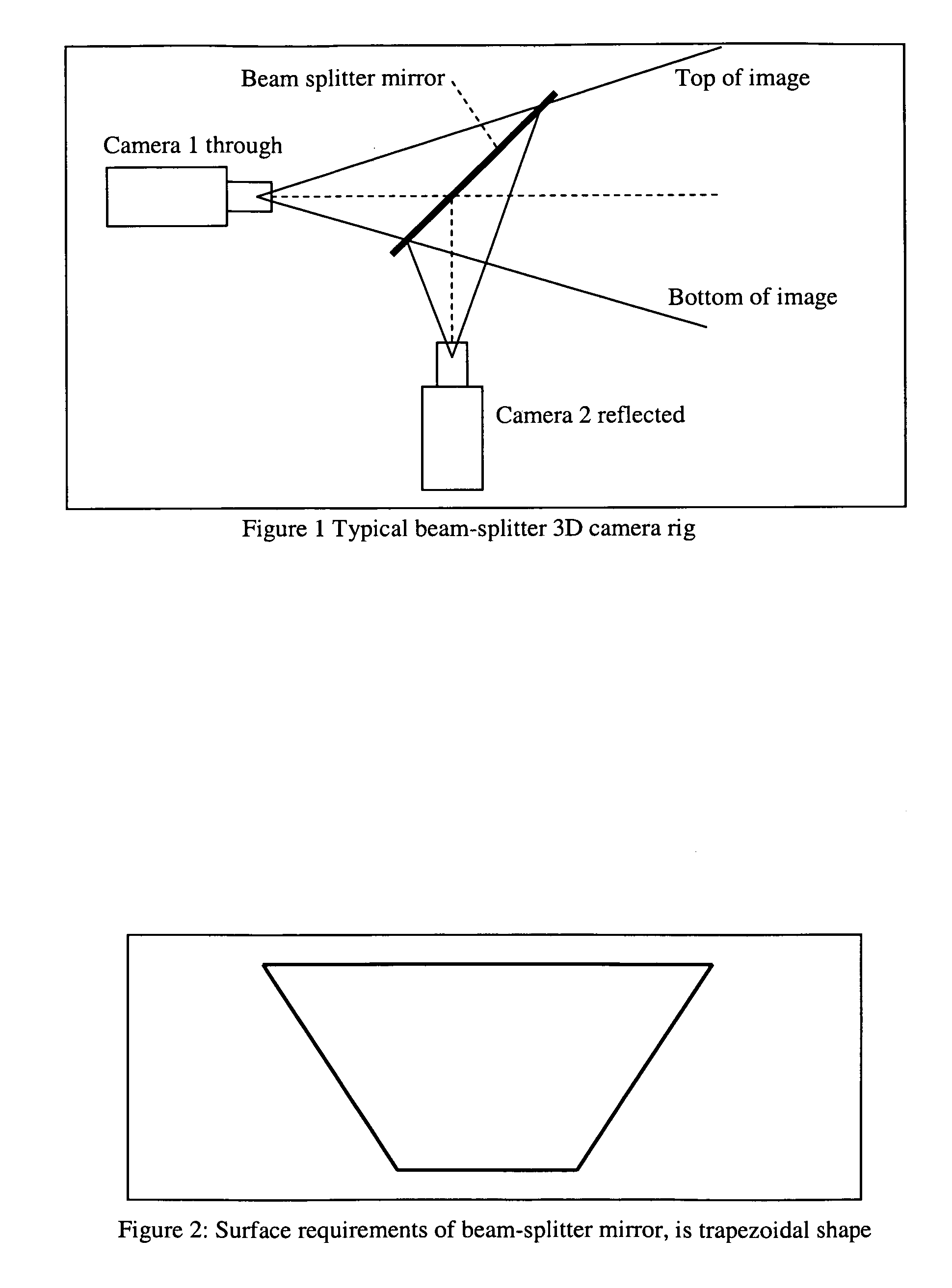
[0022] To reduce the weight and size of a beam-splitter type 3D camera rig, the beam-splitter mirror needs to be only large enough to accommodate the optical paths to the imager (CCD, CMOS of film). A typical 3d rig with a 50 / 50 beam-splitter mirror, at 45 degrees to the optical centers, is shown in FIG. 1.

[0023] It is not necessary for the beam-splitter mirror to be rectangular, as is the case with other 3D rigs. In fact, by ray-tracing the optical paths from each camera, they are bound by a pyramid shape, therefore a 45 degree intersection into this pyramid by the beam-splitter mirror creates a trapezoidal shape, as shown in FIG. 2.

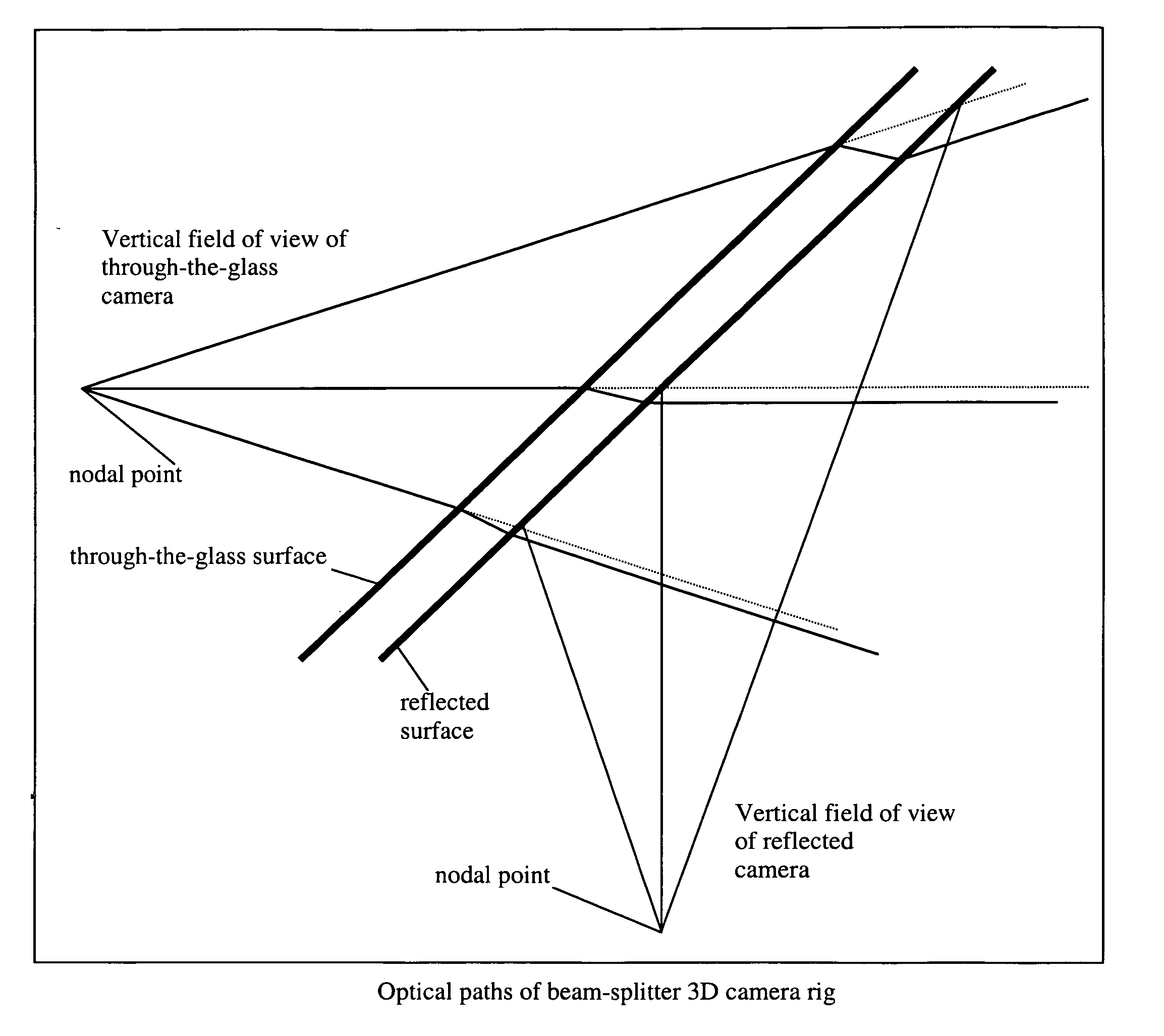
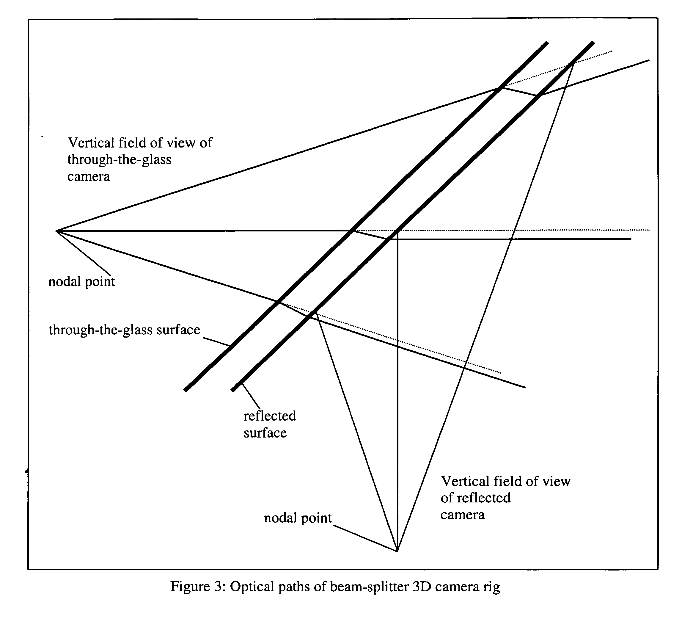
[0024] b) Beam-splitter Mirror Facing Downwards

[0025] To reduce dust collection on the surface of the mirror, and to reduce the effect of ambient light reflecting into the view of Camera 2 of FIG. 1, Camera 2 is made to look upwards, with the reflecting surface of the beam-splitter mirror facing downwards. ...


PUM


Abstract

Ongoing research and development on Stereoscopic 3D Camera rigs has led to certain new and unique improvements, including a trapezoidal beam-splitter mirror, a beam-splitter mirror that is facing downwards, a stereoscopic platform that can be inverted 180°, an optical wedge for vertical field-of-view refraction compensation, a single inter-ocular motor with dual rack-and-pinion gear system, dual convergence motors on worm gears, a convergence rotation under first-nodal point, and an electronics control mounted under the mirror.

Description

CROSS-REFERENCE TO RELATED APPLICATIONS [0001] This application claims priority to provisional application entitled, TWO CAMERA STEREOSCOPIC CAMERA PLATFORM, filed Jul. 14, 2005, having a Ser. No. 60 / 698,961, which is hereby incorporated by reference in its entirety.FIELD OF THE INVENTION [0002] The present invention relates generally to stereoscopic 3D camera systems. BACKGROUND OF THE INVENTION [0003] There are various types of stereoscopic 3D camera rigs, and the methods of configuring them vary for different designs, and 3D shooting philosophies. [0004] There are beam-splitter types, which allows the inter-ocular distance to be varied from zero to its maximum travel range. For close-up stereography, this type provides the only possible way to shoot. [0005] There are side-by-side camera types, which have their minimum inter-ocular distance limited by the size of the cameras or their lenses. This configuration does not allow close-up shooting because of this limitation. [0006] Thi...

Claims


Application Information

Patent Timeline
Patent Type & Authority Applications(United States)
IPC IPC(8): G03B35/00H04N13/239
CPCG03B35/08H04N13/0239H04N13/239
Inventor BUTLER-SMITH, BERNARD J.SCHKLAIR, STEVEN J.
Owner 3ALITY DIGITAL SYST
Why Eureka
Try Eureka