
Wireless LAN device and communication mode switching method

Inactive Publication Date: 2007-06-21
FUJITSU LTD
View PDF3 Cites 129 Cited by
  • Summary
  • Abstract
  • Description
  • Claims
  • Application Information

AI Technical Summary

Benefits of technology

[0019] The present invention was created in view of the above circumstances, and an object thereof is to provide a wireless LAN device and a communication mode switching method whereby failure in the switching from infrastructure mode to ad-hoc mode can be lessened.

Problems solved by technology

A mobile station belonging to a certain access point is unable to receive radio waves from other access points or detect a mobile station communicating using radio waves of a different access point and thus cannot switch into ad-hoc mode to communicate with such a mobile station.
During the scanning, the mobile station is unable to communicate in infrastructure mode, thus causing overhead.
Also, the scanning is basically conducted at regular intervals for updating, and therefore, a time lag inevitably occurs in the case where a new mobile station has been added.
Further, where the switching to ad-hoc mode is triggered by mobile stations, in many cases the mobile stations themselves decide to switch to ad-hoc mode in a distributed autonomous manner, which makes it difficult to ensure security as compared with the case of centralized management.
Accordingly, the switching from infrastructure mode to ad-hoc mode is tried even in cases where the mobile stations are not within each other's coverage of radio waves, giving rise to the problem that the switching often ends in failure.
However, since the mobile stations 224a and 224c are not within each other's coverage of radio waves, ad-hoc mode communication fails in the end.

Method used


Image

  • Wireless LAN device and communication mode switching method
  • Wireless LAN device and communication mode switching method
  • Wireless LAN device and communication mode switching method

Examples


first embodiment

[0062] the present invention will be now described in detail with reference to the drawings wherein the invention is applied to a wireless LAN switch as the wireless LAN device.

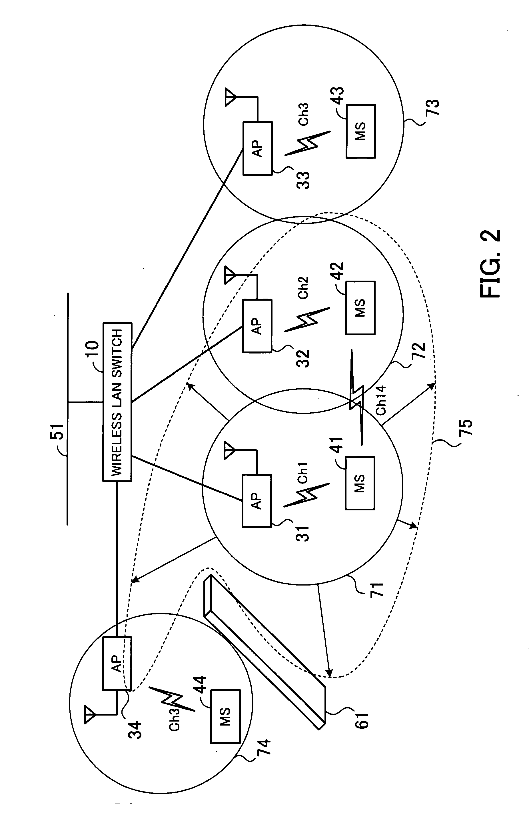
[0063]FIG. 2 shows an exemplary system configuration comprising the wireless LAN switch of the first embodiment, access points (APs), and mobile stations (MSs). As illustrated, the wireless LAN switch 10 is connected, for example, to a wired Ethernet backbone network 51. Also, the wireless LAN switch 10 is connected by wire with access points 31 to 34.

[0064] Let us suppose, for example, that the access point 31 and a mobile station 41 are communicating in infrastructure mode by using a channel Ch1, that the access point 32 and a mobile station 42 are communicating in infrastructure mode by using a channel Ch2, that the access point 33 and a mobile station 43 are communicating in infrastructure mode by using a channel Ch3, and that the access point 34 and a mobile station 44 are communicating in infrastructur...

second embodiment

[0142] the present invention will be now described in detail with reference to the drawings.

[0143] In the second embodiment, information about mobile stations that failed in ad-hoc communication is stored in an additionally provided communication failure list storage, and the mode of communication between such mobile stations is thereafter prevented from switching to ad-hoc mode. Thus, in operational environments where mobile stations are not frequently moved, failure in the switching to ad-hoc mode can be more effectively lessened.

[0144] Such operational environments where mobile stations are not frequently moved are conceivably created in offices, for example. Usually, employees work at their own desks by using notebook computers (mobile stations), and only when a meeting is held, the employees bring their notebook computers into a conference room. Namely, a mobile station is moved from the coverage of one access point to that of another, and once associated with a certain access...

third embodiment

[0157] the present invention will be now described in detail with reference to the drawings.

[0158] In the third embodiment, information about mobile stations which are not within each other's coverage of radio waves, among the mobile stations associated with an identical access point, is generated based on RTS / CTS frames which are exchanged during communication in infrastructure mode, and is stored in an additionally provided non-coverage storage. With respect to the mobile stations registered in the non-coverage storage, the first packet transmitted therefrom is not stored in the communication message storage 19, thereby saving the capacity of the communication message storage 19.

[0159]FIG. 14 shows an exemplary system configuration comprising a wireless LAN switch of the third embodiment, access points, and mobile stations. As illustrated, the wireless LAN switch 100 is connected, for example, to a wired Ethernet backbone network 132. Also, the wireless LAN switch 100 is connecte...


PUM


Abstract

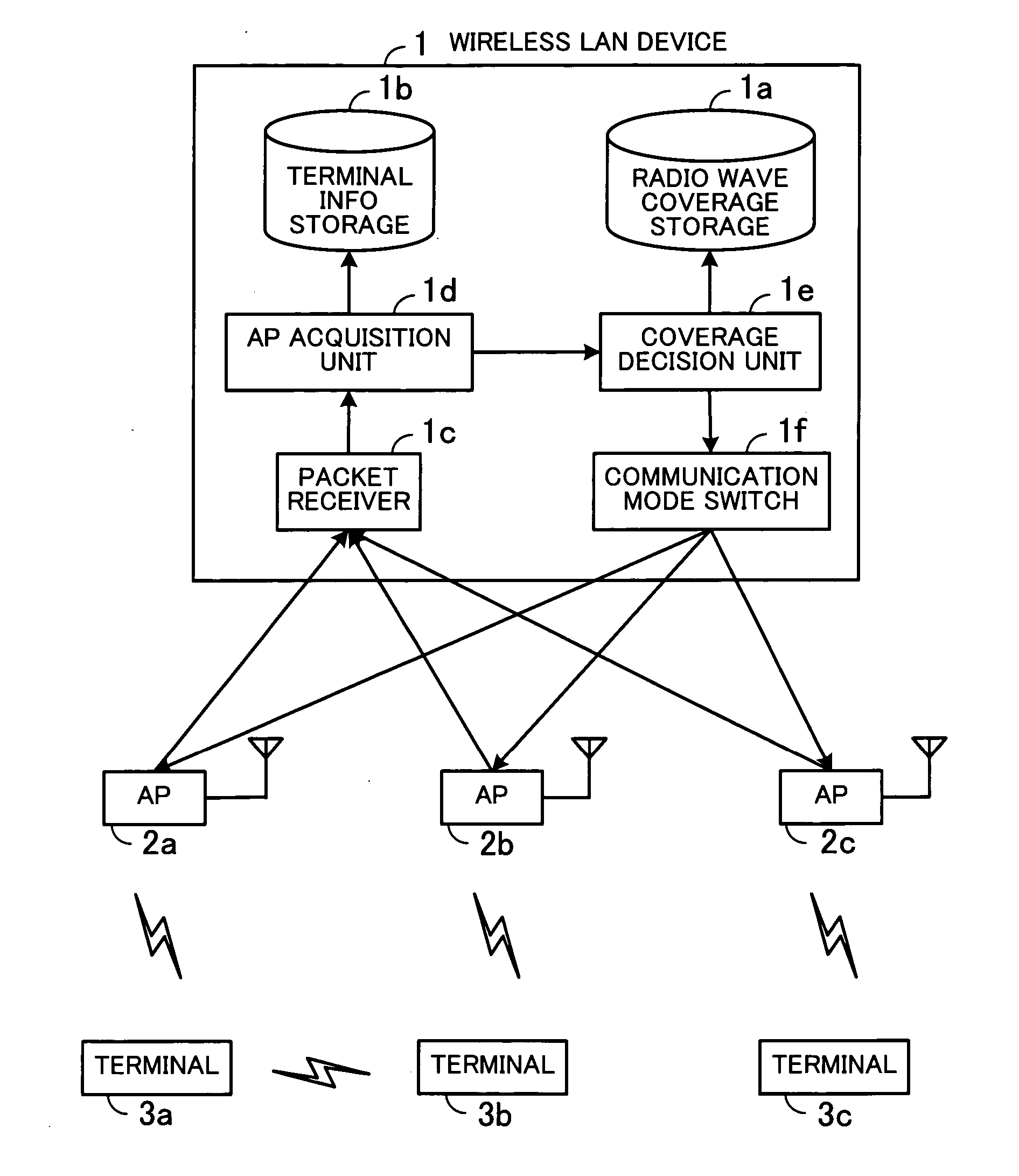
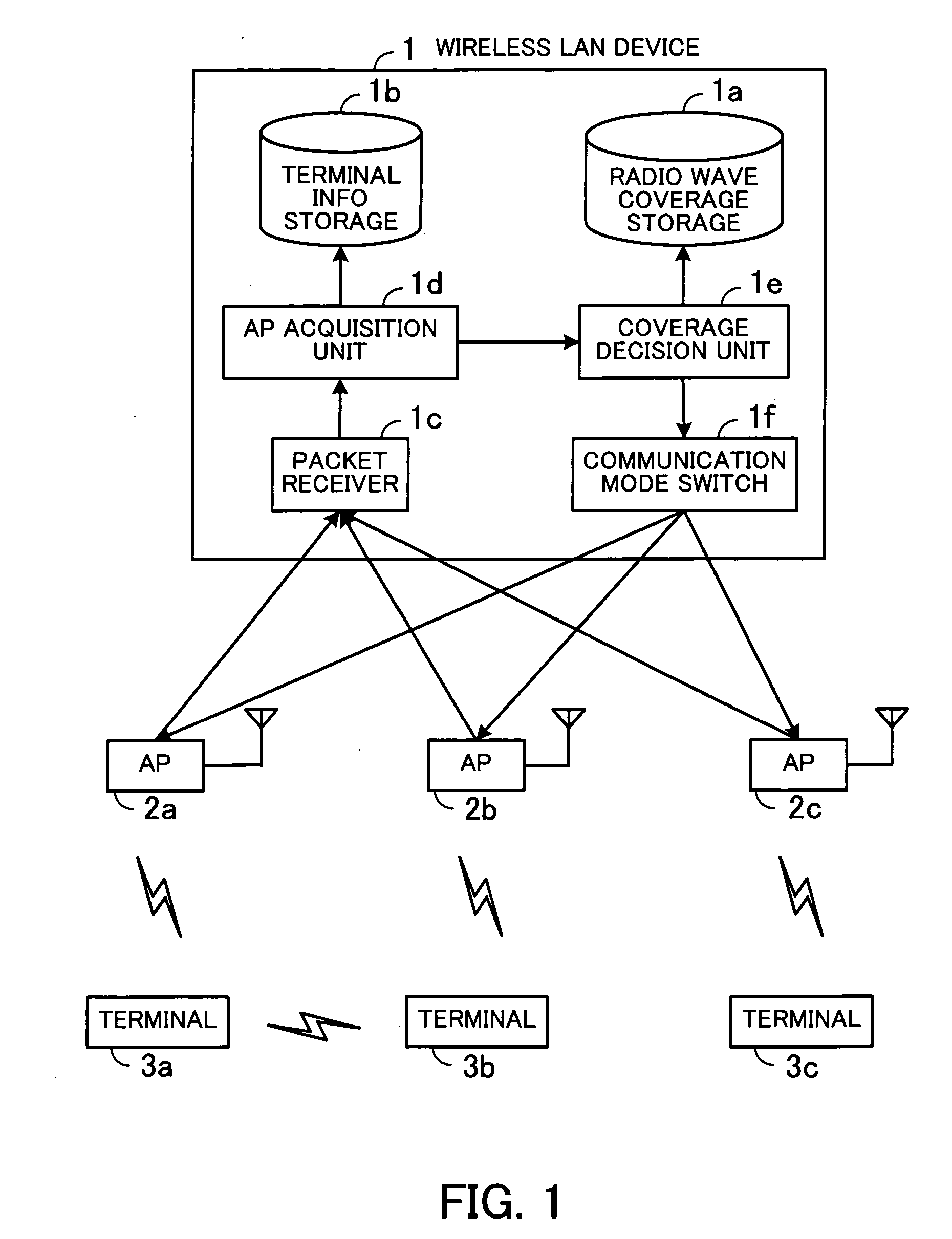
A wireless LAN device for lessening failure in switching from infrastructure mode to ad-hoc mode. A radio wave coverage storage stores coverage information about coverage of radio waves amongst access points. A terminal information storage stores terminal information about terminals associated with the access points. A packet receiver receives, via the access points, a packet transmitted from any of the terminals in infrastructure mode. An access point acquisition unit looks up the terminal information storage, based on terminal information about originating and destination terminals contained in the packet, to identify access points with which the terminals are associated. A radio wave coverage decision unit looks up the radio wave coverage storage to determine whether the identified access points are within each other's coverage of radio waves. A communication mode switch switches the communication mode of the originating and destination terminals to ad-hoc mode in accordance with the determination result.

Description

CROSS-REFERENCE TO RELATED APPLICATIONS [0001] This application is based upon and claims the benefits of priority from the prior Japanese Patent Application No. 2005-362847 filed Dec. 16, 2005, the entire contents of which are incorporated herein by reference. BACKGROUND OF THE INVENTION [0002] 1. Field of the Invention [0003] The present invention relates to wireless LAN devices and communication mode switching methods, and more particularly, to a wireless LAN device for controlling a plurality of access points and a communication mode switching method for such a wireless LAN device. [0004] 2. Description of the Related Art [0005] Wireless LAN (Local Area Network) is known as a typical example of networks enabling wireless communication between terminals. Representative specifications of wireless LANs have been formulated by the IEEE (Institute of Electrical and Electronic Engineers) as IEEE 802.11a, IEEE 802.11b / g, etc. Currently, these types of wireless LANs are widely used at ho...

Claims


Application Information

Patent Timeline
IPC IPC(8): H04Q7/24H04W72/04H04W84/12H04W84/18
CPCH04W84/12H04W84/18H04W76/043H04W88/08H04W88/12H04W8/005H04W76/23
Inventor KOJIMA, YUJI
Owner FUJITSU LTD
Learn More