Curtain coater and curtain coating method

a curtain and coating technology, applied in the field of curtain coating, to achieve the effect of reducing the peripheral

Inactive Publication Date: 2007-06-21
POLYTYPE CONVERTING
View PDF10 Cites 24 Cited by
  • Summary
  • Abstract
  • Description
  • Claims
  • Application Information

AI Technical Summary

Benefits of technology

[0019] It is an object of the invention to reduce peripheral effects which adversely affect the coating result.
[0020] In particular, it is an object to provide a side guide for a fluid curtain which more exactly determines the line of fall of the curtain as compared to a plate-shaped side guide, but which nonetheless keeps tension forces in the curtain low. Border coat effects should be reduced.
[0027] Mobility should be provided at least crossways to the conveying direction of the substrate for the purpose of adjusting the width of the curtain. Mobility for adjusting the height of the guiding face is likewise advantageous. Lastly, an adjustment in and counter to the conveying direction of the substrate is also advantageous.
[0029] In a further development, the current ratios in the coating fluid or in the multiple-coat coating fluids are improved not only in the peripheral zone of the curtain current but also in the peripheral zone of the film current of the nozzle device. The improvement is aimed at nozzle devices which comprise a nozzle surface inclined to the horizontal, an exit opening through which the coating fluid of the nozzle surface can be supplied such that the coating fluid forms a downward-flowing film current on the nozzle surface, also a nozzle lip which forms a downstream end of the nozzle surface at which the film current transitions into the curtain current, and lastly a nozzle side boundary for laterally restricting the film current flowing on the nozzle surface. According to the invention, the nozzle side boundary exhibits throughout—from the nozzle lip as far as a point upstream of the nozzle lip—a height, measured to the nozzle surface, which at least substantially, preferably precisely, corresponds to the respectively local thickness of the free film current outside the border coat on the side boundary. Adapting the boundary height to the thickness of the free film current, which changes in its course, i.e. to its equilibrium thickness, causes the film current to neither flow over the nozzle side boundary nor be drawn up it due to capillary action. This can reduce flows of material crossways to the current direction pointing to the nozzle lip.
[0030] The longitudinal section of the nozzle side boundary, which is adapted in this way to the thickness of the free film current, preferably extends at least as far as the exit opening. If a number of exit openings are provided in succession in the current direction, for forming a multiple-coat film current, the longitudinal section of the nozzle side boundary adapted in height in this way should extend as far as the most upstream point at which one coat flows onto the next, preferably as far as the most upstream of the exit openings. The less the film current on the nozzle surface is interfered with along the nozzle side boundary, and the less the thickness of the fluid film is therefore non-uniform along the nozzle side boundary due to capillary effects, the more uniformly the fluid curtain formed below the nozzle lip can be set.

Problems solved by technology

Since, on the other hand, the curtain can migrate along the guiding face, crossways to the face of the curtain, the tension forces generated by this in the curtain are smaller than with a rod-shaped, i.e. lineal side guide which does not allow the curtain to give at its periphery due to the effect of interference forces.

Method used


Image

  • Curtain coater and curtain coating method
  • Curtain coater and curtain coating method
  • Curtain coater and curtain coating method

Examples


Embodiment Construction

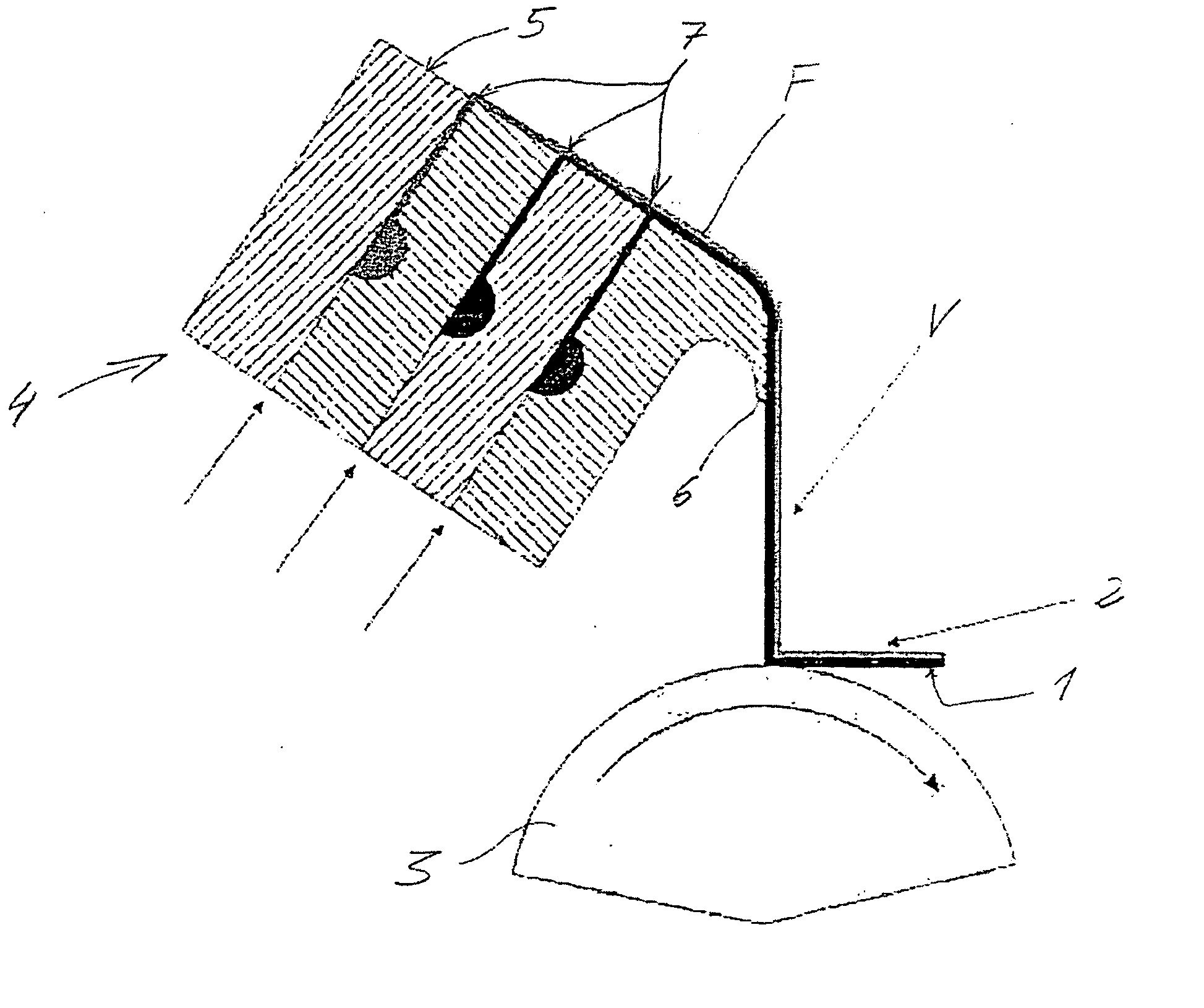
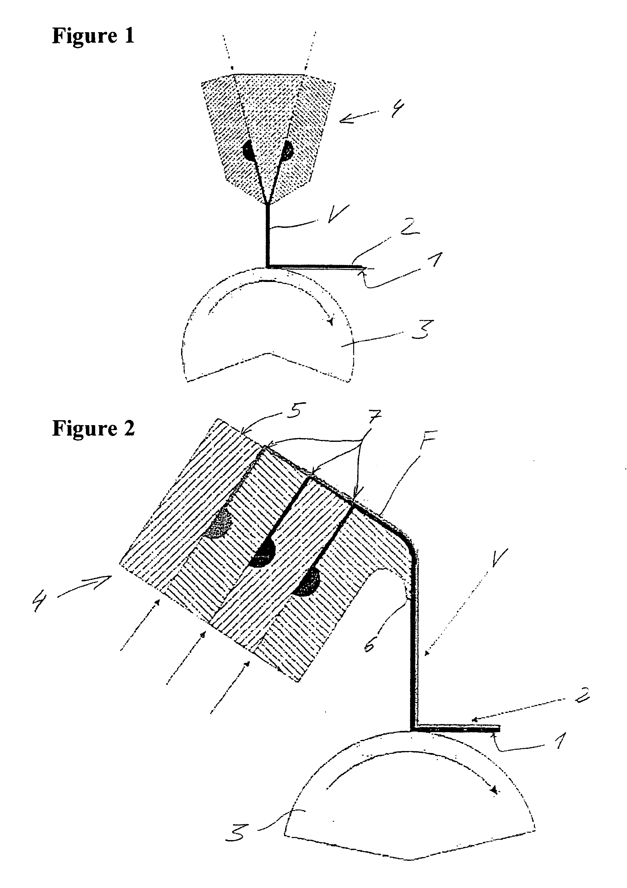
[0047]FIG. 1 shows a curtain coater comprising a nozzle device 4 arranged vertically above a roller 3 at a clear distance. The roller 3 serves as a deflection means or, in more general terms, as a supporting means for a substrate 1 to be coated, which is conveyed via the roller 3, which it wraps around. The substrate 1 is a continuously conveyed, flexible web. The nozzle device 4 is a slit nozzle in which separate supplies are formed for a number of—in the example embodiment, two—different coating fluids. The supplies converge in a nozzle exit opening at a lower end of the nozzle device 4 facing the substrate 1. The exit opening extends slit-shaped, crossways to the conveying direction of the substrate 1, over a width which is greater than the target coating width of the product formed from the substrate 1 and the coating 2. In principle, however, the width of such an exit opening can also be smaller than the target coating width. The two coating fluids leave the exit opening of the...


PUM


Abstract

A curtain coating device for the coating of a moving substrate, comprising a nozzle device, for the generation of a curtain dropping onto the substrate, made up of at least one coating fluid and a curtain guide structure with a guide surface, which laterally guides the curtain, whereby the guide surface is convex to the curtain along a width exceeding the depth of the curtain when measured transversely. Additionally, a curtain coating method, whereby a curtain made up of at least one coating fluid is deposited on a moving substrate in free fall and guided on both sides by means of a convex guide surface transverse to the curtain.

Description

[0001] This application is the U.S. national phase application of PCT International Application No. PCT / EP2005 / 003375, filed Mar. 31, 2005, and claims priority to German Patent Application No. 10 2004 016 923.3, filed on Apr. 6, 2004.BACKGROUND OF THE INVENTION [0002] 1. Technical Field. [0003] The invention relates to a device and a method for curtain coating a substrate which is moved, preferably a flexible, continuously conveyed web. [0004] 2. Description of the Related Art. [0005] Curtain coating is one of many methods for coating flexible, continuous webs with a thin fluid film. The method is suitable for applying a coat of a single fluid or a number of coats of various fluids at the same time. The curtain coating method has been known and researched for many years. A detailed description is provided for example by Miyamoto and Katagiri, Curtain Coating, in Liquid Film Coating, Chapter 11c, Chapman & Hall, New York 1997. In industrial applications, the curtain is either wider o...

Claims


Application Information

Patent Timeline
IPC IPC(8): B05D1/30B05C3/02B05C5/00B05C9/06G03C1/74
CPCB05C5/005B05C5/008B05C9/06G03C2001/747
Inventor SCHWEIZER, PETERKREBS, FERDINANDKOESTINGER, MARCEL
Owner POLYTYPE CONVERTING
Why Eureka
Try Eureka