
Fin unit for a cooler

Inactive Publication Date: 2007-06-14
TSAI HUA HSIN
View PDF8 Cites 16 Cited by
  • Summary
  • Abstract
  • Description
  • Claims
  • Application Information

AI Technical Summary

Benefits of technology

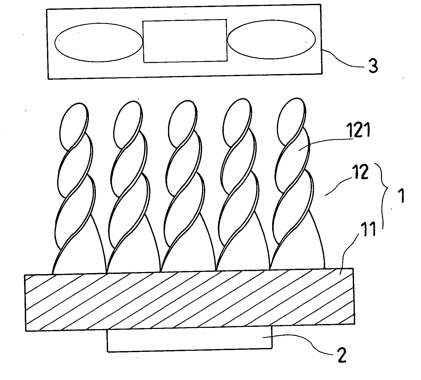
[0007] The objective of the invention is to offer a fin device for a cooler, including a heat-conducting unit, a plurality of helical elongated twisted fins and a fan. The heat-conducting member or the heat generator has its surface fixed with the plurality of helical elongated twisted fins, and the fan is assembled above the helical elongated twisted fins. The fan is started to operate and actuate the surrounding air to produce air convection among the helical elongated twisted fins to form helical whirls to increase contact and collision of the air with the helical elongated twisted fins, thus achieving excellent effect of heat dissipation.

Problems solved by technology

But one thing that cannot be neglected is the increase of heat energy, and the fact is that the faster the processing speed of the CPU is, the higher the temperature of the CPU becomes.
If the temperature of the CPU rises continuously, it will affect the processing speed and lower the work efficiency of the CPU and make the computer hang or down and even cause the CPU to be burned down.
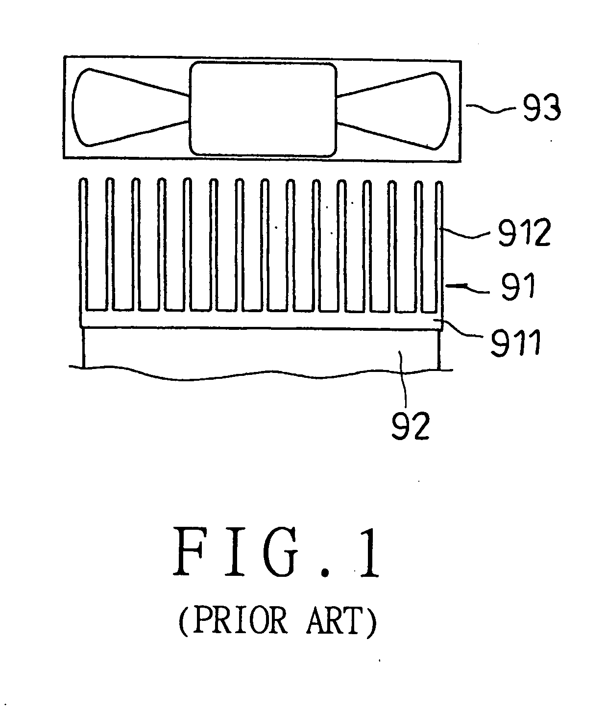
However, since the fins of a conventional cooler are thin plates positioned side by side equidistantly; therefore, when the fan is started to actuate the surrounding air to produce air convection, the air can only be sucked to flow upward from under so only a little of the air may collide and contact with the fins, thus having little effect in heat dissipation.
Therefore, many computer users are not satisfied with the heat dissipating effect of the conventional cooler because it is likely to render the computer hang or down and cause loss of data when the temperature of the CPU rises excessively high and heat dissipation of the CPU is imperfect.

Method used


Image

  • Fin unit for a cooler
  • Fin unit for a cooler
  • Fin unit for a cooler

Examples


Embodiment Construction

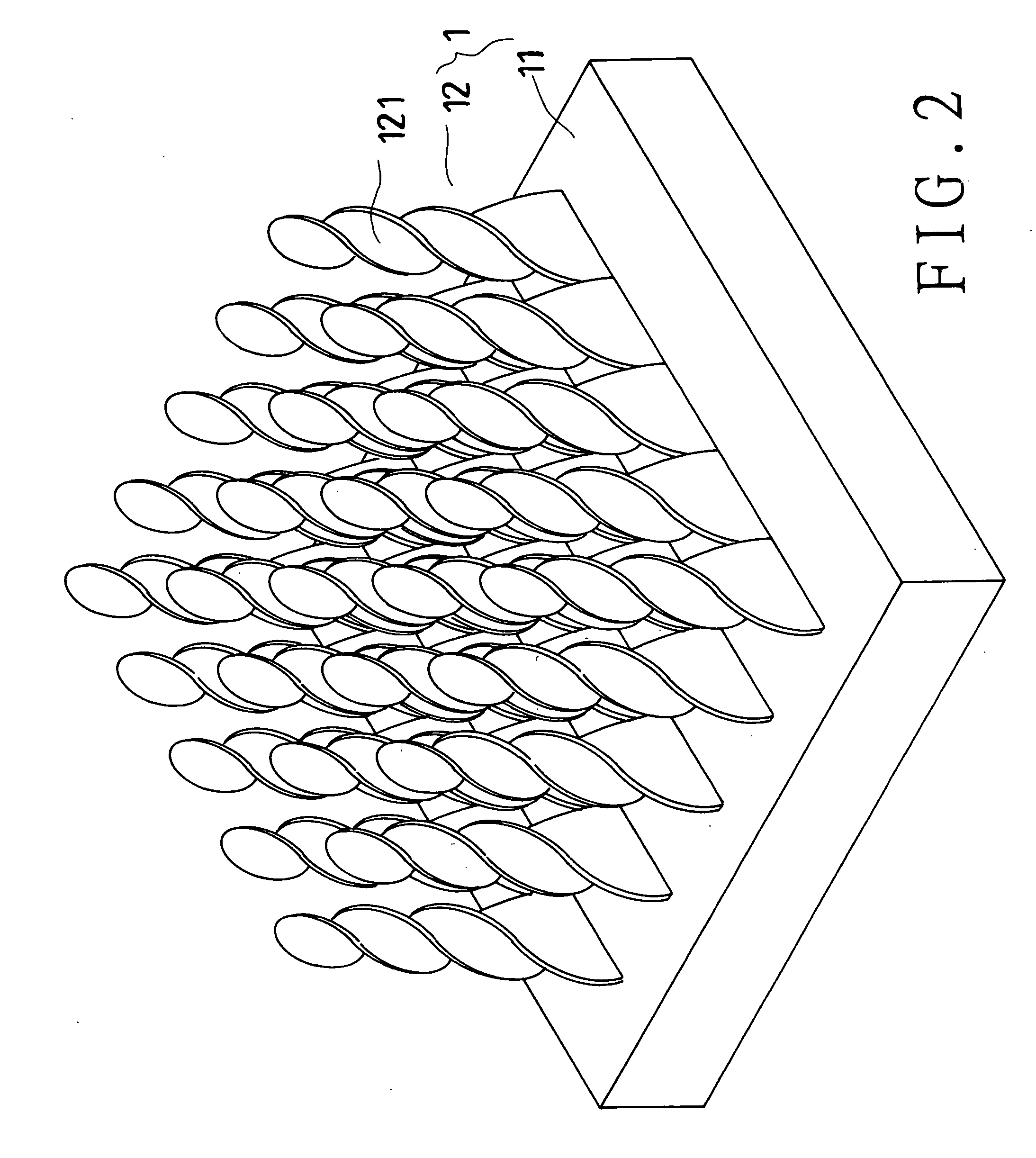
[0014] A first preferred embodiment of a fin unit for a cooler 1 in the present invention, as shown in FIGS. 2 and 3, is assembled on a heat generator 2. The fin unit is composed of a heat-conducting member 11, fins 12 and a fan 3. The heat-conducting member 11 is a flat plate horizontally positioned on the heat generator 2 and the fan 3 is assembled above the fins 12.

[0015] The fins 12 are cut, drawn and twisted to form helical elongated twisted fins 121. Thus, when the fan 3 is started to operate, the surrounding air will be actuated to produce air convection among the helical elongated twisted fins 121 to form helical whirls to increase contact and collision of the air with the helical elongated twisted fins 121 for elevating effect of heat dissipation.

[0016] In using, firstly, the flat-plate heat-conducting member 11 of the fin unit 1 is horizontally positioned on the heat generator 2 and the fan 3 is assembled above the helical elongated twisted fins 121. Then, the fan 3 is s...


PUM


Abstract

A fin unit for a cooler includes a heat-conducting member, a plurality of helical elongate twisted fins and a fan. The heat-conducting member or a heat generator has its surface fixed with the plurality of helical elongated twisted fins. When the fan is started to operate, air convection is produced among the helical elongated members, forming helical whirls to increase contact and collision of the air with the helical elongated twisted fins, enhancing effect of heat dissipation.

Description

BACKGROUND OF THE INVENTION [0001] 1. Field of the Invention [0002] This invention relates to a fin unit for a cooler, particularly to one having the surface of a heat-conducting member or the surface of a heat generator fixed with a plurality of helical elongated twisted fins, having excellent effect of heat dissipation. [0003] 2. Description of the Prior Art [0004] Generally, a CPU is the most important element of a computer. When a computer system is started to operate, the CPU will read the commands and the data of various kinds of software from a memory. After logic and mathematical operation, the UPU will store the result in the memory, and will attain the object of data processing through communication of the mother-board and the peripheral devices, Therefore, any work in the interior of the mainframe of a computer cannot be accomplished unless it is processed by the CPU, and the faster the processing speed of the CPU is, the more efficient the computer becomes. But one thing...

Claims


Application Information

Patent Timeline
IPC IPC(8): H05K7/20
CPCG06F1/20H01L23/3677H01L2924/0002H01L2924/00
Inventor TSAI, MING-KUN
Owner TSAI HUA HSIN
Learn More