Rotorcraft blade provided with a flap tiltable with the help of at least one main ball joint having a first pin that is secured to said blade

a technology of rotorcraft blades and flaps, which is applied in the direction of rotocrafts, liquid fuel engines, propellers, etc., can solve the problems of unusable and dangerous, noise or vibration disturbance, and premature wear

Inactive Publication Date: 2007-06-07
EUROCOPTER
View PDF7 Cites 10 Cited by
  • Summary
  • Abstract
  • Description
  • Claims
  • Application Information

AI Technical Summary

Benefits of technology

[0014] An object of the present invention is to propose an active blade provided with a flap that makes it possible to overcome the above-mentioned limitations of blades.

Problems solved by technology

Nevertheless, under the effect of the stresses exerted on the blade and on the flap in flight, in particular those caused by beating movements, there is a risk of the flap sliding along the bearing point which could lead to premature wear, or even, in a worse-case scenario, to the flap becoming jammed, thereby making it unusable and dangerous.
Furthermore, it can readily be seen that the overall shape of the flap, and more particularly of its leading edge, is not optimized from an aerodynamic point of view and that might possibly lead to noise or vibration disturbance and to degraded aerodynamic performance.
The connecting rod is thus situated in part outside the blade-and-flap assembly, which is harmful to overall aerodynamics.
In this second type of architecture, the means enabling the flap to pivot about a shaft still present the drawback of it being possible for the flap to jam.
Consequently, there is a non-negligible risk of the shaft being deformed, and under such circumstances the flap could then no longer be tilted to the desired angle of inclination.
Nevertheless, as for the second type of blade, the stub axles about which the flap tilts do not appear to present sufficient overall robustness to guarantee proper operation of the system over a reasonable length of time.

Method used


Image

  • Rotorcraft blade provided with a flap tiltable with the help of at least one main ball joint having a first pin that is secured to said blade
  • Rotorcraft blade provided with a flap tiltable with the help of at least one main ball joint having a first pin that is secured to said blade
  • Rotorcraft blade provided with a flap tiltable with the help of at least one main ball joint having a first pin that is secured to said blade

Examples


first embodiment

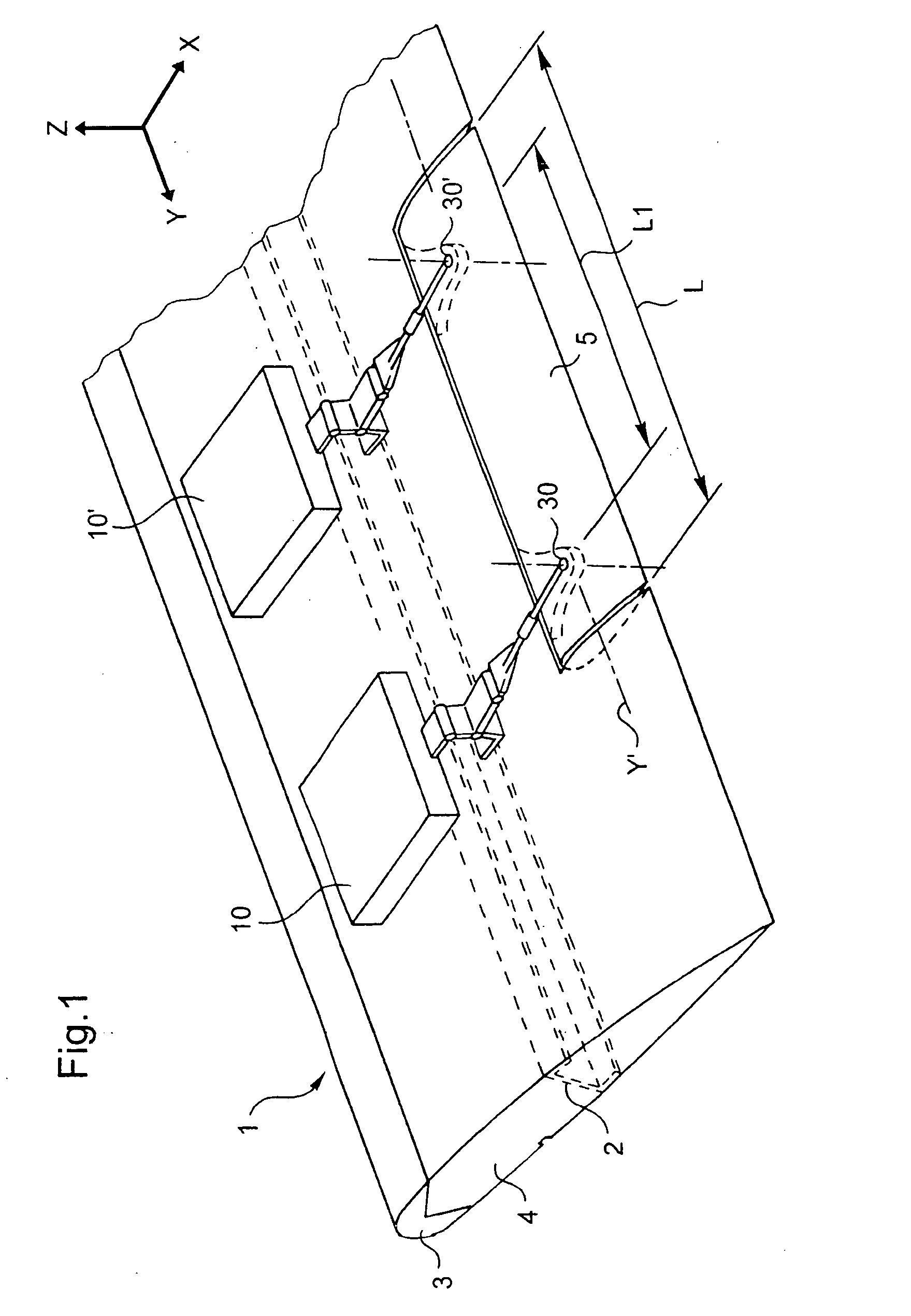
[0037]FIG. 1 is a diagrammatic isometric view showing the invention.

[0038] A rotorcraft blade 1 is provided with a trailing edge flap 5. In addition, two electromagnetic actuators 10 and 10′ are disposed inside the box 4 of the blade 1 disposed between the front spar 3 and the channel-section rib 2 of the blade 1.

[0039] The actuators 10 and 10′ enable the trailing edge flap 5 to pivot about a virtual hinge axis Y′ in order to improve the aero-acoustic, aerodynamic, and vibratory performance of the blade 1. The actuators are themselves controlled by an electronic unit (not shown in the figures) that delivers the flap-control relationship (tilt angle / frequency) as a function of the flight configuration of the rotorcraft. The actuators 10 and 10′ are powered electrically via slip rings disposed in the rotorcraft rotor and via an electrical circuit integrated in the blade 1 along its span.

[0040] In active mode, position sensors deliver signals to the electronic unit to enable it to se...

second embodiment

[0065] With reference to FIG. 5, in a second embodiment, the extensible flexible pivot comprises a spring 45 with turns that are touching at rest. This spring makes it possible both for movements to take place along the axis X and for the crank 41 and the second connecting rod 44 to pivot. The spring presents sufficient stiffness to avoid it becoming deformed as a result of the stresses exerted on the blade 1.

[0066] Furthermore, the extensible pivot is advantageously coated in an elastomer material (not shown in FIG. 5) serving to improve the strength of the extensible pivot while also preserving its flexibility.

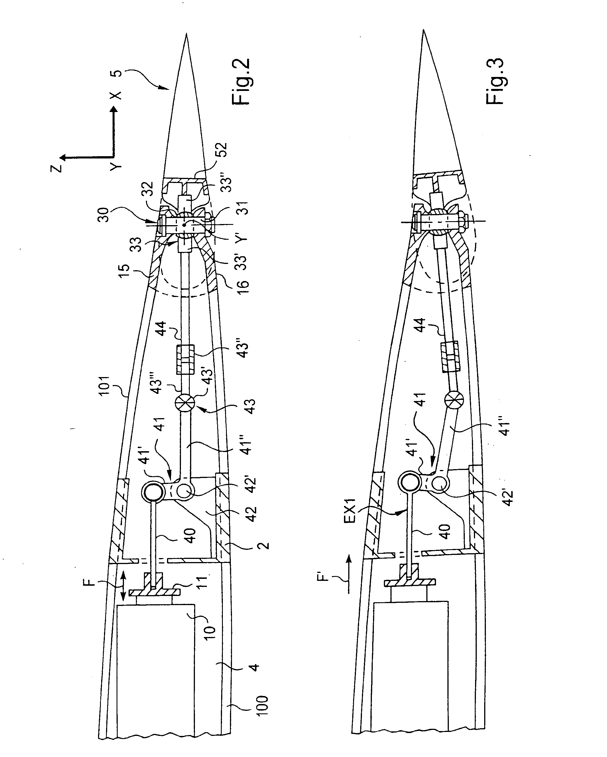
[0067] The movement of this second embodiment is then substantially equivalent to that described with reference to FIG. 3.

[0068] Naturally, the present invention can be subjected to numerous variants as to its implementation. Although several embodiments are described above, it will naturally be understood that it is not conceivable to identify exhaustively all possible em...


PUM


Abstract

The present invention relates to a rotorcraft rotor blade (1) including at least one tiltable trailing-edge flap (5), said flap (5) being suitable for pivoting about a virtual hinge axis (Y′) extending substantially along the span of said blade (1) and of said flap (5). The blade (1) is remarkable in that it is provided with at least one main ball joint (30) provided with an inner cage (32) together with a first pin (31) and an outer cage (33), the front portion (33′) of said outer cage (33) of the main ball joint (30) being connected to a linear actuator (10, 10′) arranged in said blade (1) and serving to pivot said flap (5), said first pin (31) of the main ball joint (30) being substantially perpendicular to said virtual hinge axis (Y′) about which said flap (5) pivots.

Description

[0001] The present invention relates to an active rotorcraft blade provided at its trailing edge with a flap that is tiltable with the help of at least one main ball joint, the flap being controlled locally by an electromechanical device including a linear actuator. BACKGROUND OF THE INVENTION [0002] In order to improve the aero-acoustic, vibratory, and aerodynamic performance of the blades of a main lift and advance rotor of a rotorcraft, it is advantageous to place a tiltable flap in the trailing edge of each blade, which flap is conveniently referred to as a trailing edge flap. [0003] The angle through which the flap can be tilted relative to the blade is of the order of ±10° at a frequency of about 30 hertz (Hz). To be effective, the angle of tilt varies actively over time as a function of numerous parameters such as the position of the blade about the axis of the main rotor, referred to as the “azimuth” position, the speed of rotation of the main rotor, and the pitch, beating, ...

Claims


Application Information

Patent Timeline
Patent Type & Authority Applications(United States)
IPC IPC(8): B64C27/615
CPCB64C27/615B64C27/72Y02T50/34B64C2027/7272Y02T50/30
Inventor GRANDMAISON, FRANCOIS LORIN DE LAMORANT, MICHELARDESI, OLIVIERGAFFIERO, JACQUES
Owner EUROCOPTER
Why Eureka
Try Eureka