Method of producing laminate-type piezoelectric element

a piezoelectric element and laminate technology, applied in the direction of variable capacitors, machines/engines, generators/motors, etc., can solve the problems of affecting the performance of the piezoelectric element, so as to and reduce the occurrence of cracks

Inactive Publication Date: 2007-06-07
DENSO CORP
View PDF9 Cites 8 Cited by
  • Summary
  • Abstract
  • Description
  • Claims
  • Application Information

AI Technical Summary

Benefits of technology

[0009] The present invention was accomplished in view of the above problems in the prior art and provides a method, of producing a laminate-type piezoelectric element, which is capable of easily forming a structure for effectively relaxing the stress caused by piezoelectric displacement and is, further, capable of providing excellent durability and reliability.

Problems solved by technology

Therefore, stress (strain) is concentrated in the non-overlapped portion depending upon the piezoelectric displacement, and cracks may occur in the ceramic laminated body.
Also, there may occur an inconvenience such as an insulation breakdown.
However, the stress relaxing portions in the above patent publications are filled with, for example, fine lead titanate particles which may migrate upon being repetitively driven and may be detrimental to the performance of the piezoelectric element.
According to this patent publication, however, the recessed grooves are formed by machining which is not suited for mass production.
Besides, cracks develop on the machined surfaces which may become a cause of an inconvenience such as an insulation breakdown.

Method used


Image

  • Method of producing laminate-type piezoelectric element
  • Method of producing laminate-type piezoelectric element
  • Method of producing laminate-type piezoelectric element

Examples


example 1

[0088] A method of producing a laminate-type piezoelectric element according to an embodiment of the first invention will be described with reference to the drawings.

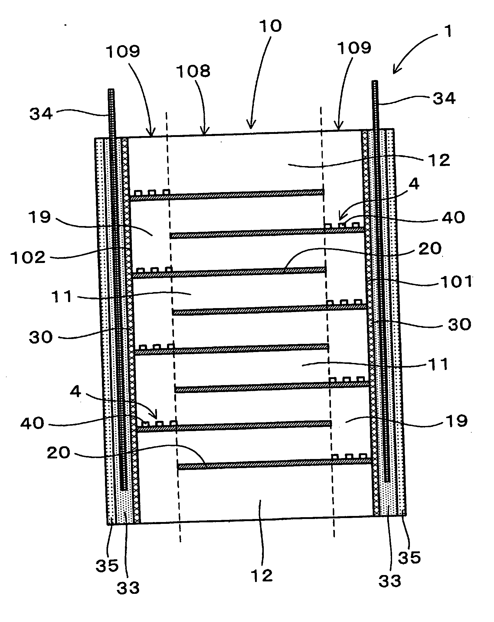
[0089] The method of producing a laminate-type piezoelectric element 1 is a method of producing the laminate-type piezoelectric element 1 which, as shown in FIGS. 1 to 13, has a ceramic laminated body 10 obtained by alternately laminating piezoelectric layers 11 made of a piezoelectric material and inner electrode layers 20 having electrically conducting property, and having outer electrodes 34 arranged on the side surfaces 101 and 102 of the ceramic laminated body 10.

[0090] The ceramic laminated body 10 is formed through an intermediate laminated body-forming step of forming an intermediate laminated body 100 by alternately laminating green sheets 110 that serve as the piezoelectric layers 11 and the inner electrode layers 20, and a calcining step of forming the ceramic laminated body 10 by calcining the intermediate...

example 2

[0141] A method of producing the laminate-type piezoelectric element according to an embodiment of the second invention will be described with reference to the drawings.

[0142] The method of producing the laminate-type piezoelectric element 1 includes, as shown in FIGS. 15 to 22, the intermediate laminated body-forming step and the calcining step as in Example 1.

[0143] In the intermediate laminated body-forming step, there are formed an overlapped portion 108 and a non-overlapped portion 109 in the intermediate laminated body 100, and a material 42 is arranged on at least a portion in the non-overlapped portion 109 for forming relaxing layers having a calcining temperature lower than that of the green sheet 110 and contracting greatly in the calcining step. In the calcining step, further, relaxing layers 4 including voids 40 are formed by having the material 42 for forming relaxing layers contract more than the neighboring portions.

[0144] This will now be described in detail.

[014...

example 3

[0171] This Example is concerned with a method of producing the laminate-type piezoelectric element 1 of Example 1 and wherein the relaxing layers 4 including voids 40 are formed at intermediate positions among the inner electrode layers 20. The contents thereof will be described with reference to the drawings.

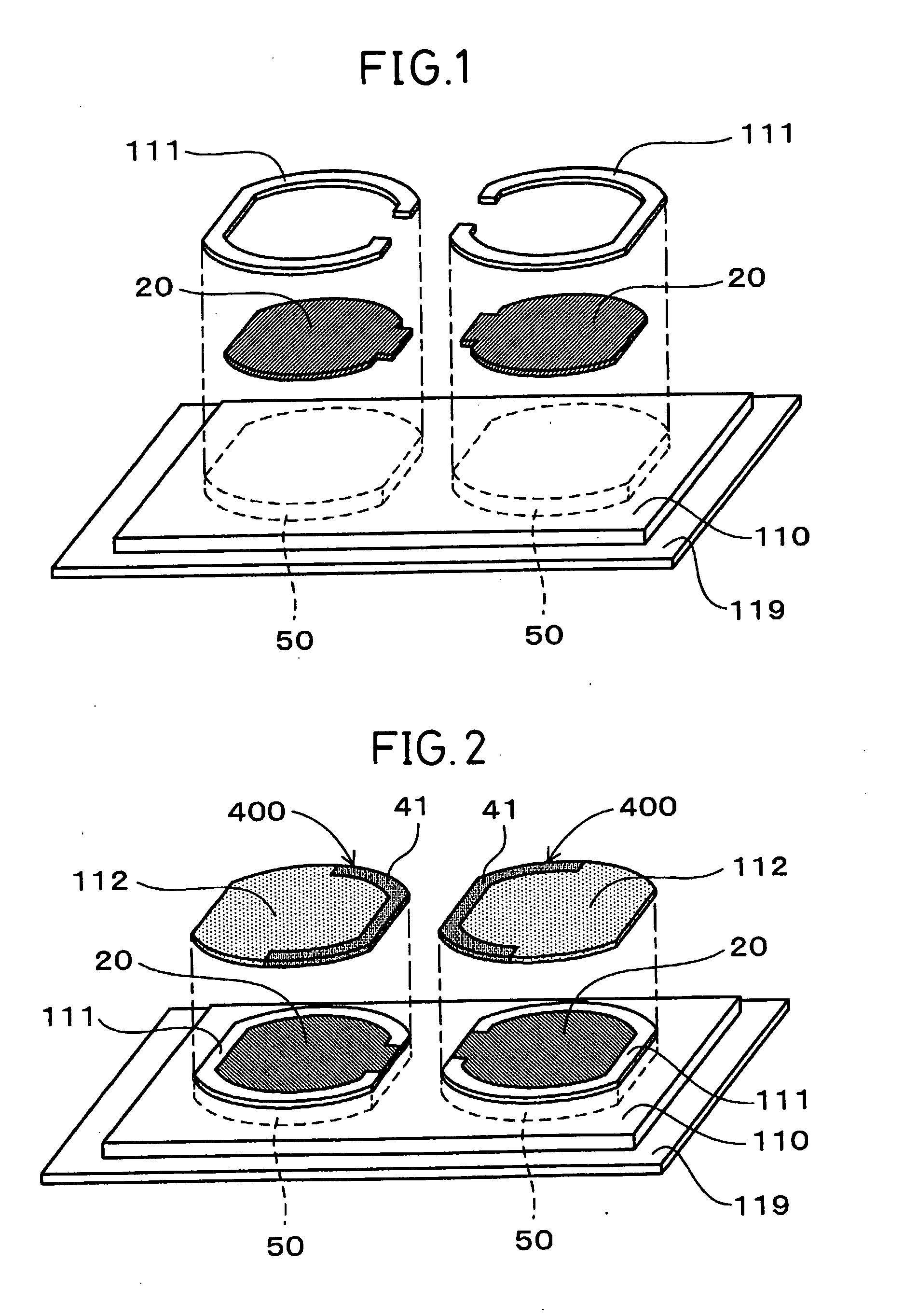
[0172] In the electrode-printing step and in the adhesive layer-printing step of this Example as shown in FIG. 23, an inner electrode layer 20, a spacer layer 111 and an adhesive layer 112 are printed on the punching regions 50 of the green sheet 110 in order to obtain two kinds of sheet pieces, i.e., an electrode-including sheet piece 53 on which the inner electrode layer 20 is printed and a relaxing layer-forming sheet piece 54 for forming the relaxing layer 4.

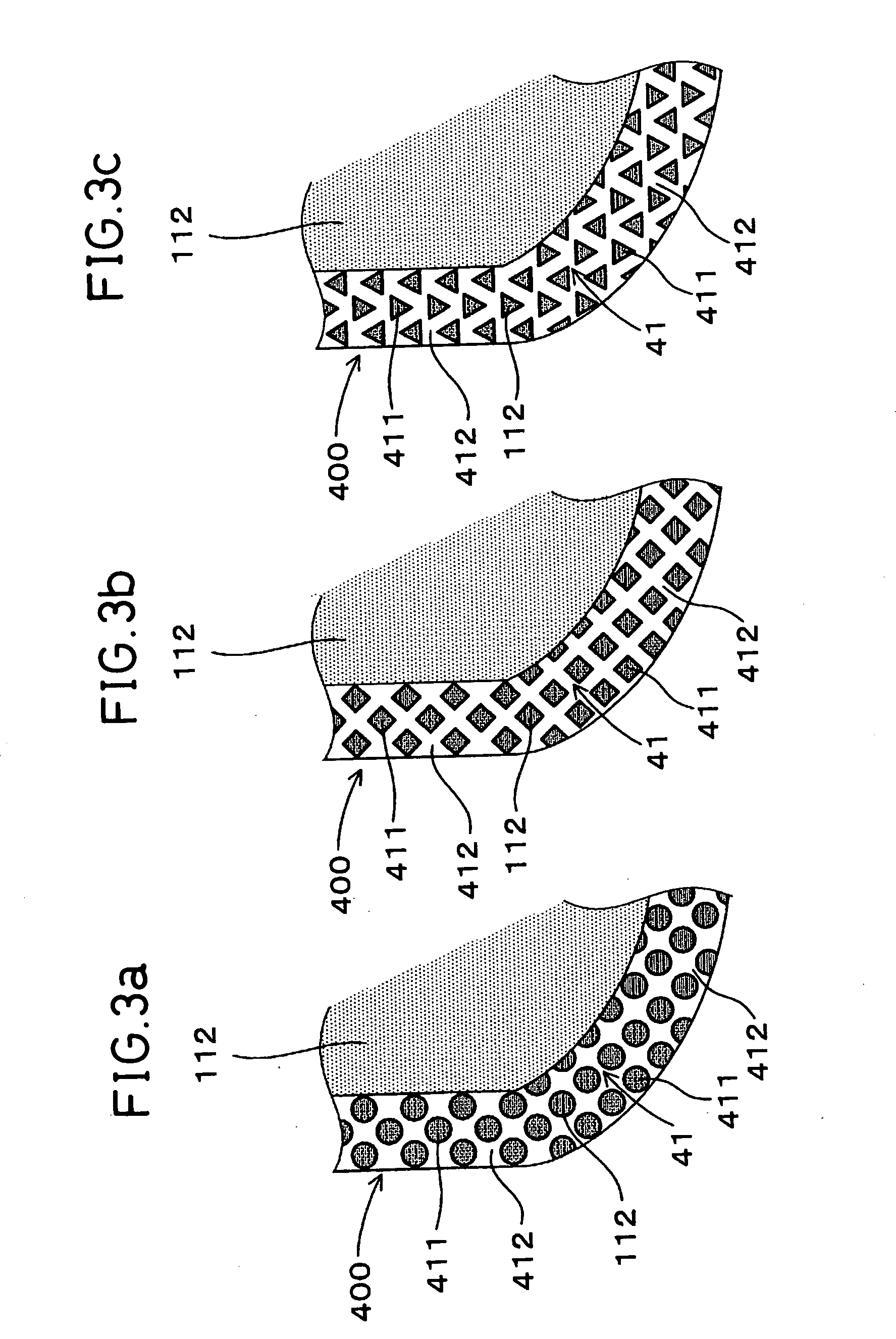
[0173] As shown, the inner electrode layer 20 and the spacer layer 111 are screen-printed on the punching regions 50 of the green sheet 110 for forming the electrode-including sheet pieces 53. The adhesive layer 112 ...


PUM

PropertyMeasurementUnit
particle sizeaaaaaaaaaa
temperatureaaaaaaaaaa

Abstract

A method of producing a laminate-type piezoelectric element, wherein a ceramic laminated body therein is formed through an intermediate laminated body-forming step of forming an intermediate laminated body 100 by alternately laminating green sheets 110 that serve as the piezoelectric layers and the inner electrode layers 20, and a calcining step of forming the ceramic laminated body by calcining the intermediate laminated body 100. In the intermediate laminated body-forming step, an overlapped portion 108 and a non-overlapped portion 109 are formed in the intermediate laminated body 100, and voids 40 are formed, in advance, in at least part of the portion that becomes the non-overlapped portion 109. In the calcining step, relaxing layers including the voids 40 are formed.

Description

TECHNICAL FIELD [0001] The present invention relates to a method of producing a laminate-type piezoelectric element which can be applied to, for example, piezoelectric actuators and the like. BACKGROUND ART [0002] In recent years, injectors, for fuel injection for automobiles, using laminate-type piezoelectric elements have been developed from the standpoint of improving fuel efficiency, exhaust gas emission, etc. of automobiles. [0003] The laminate-type piezoelectric element has a ceramic laminated body obtained by alternately laminating piezoelectric layers made of, for example, a piezoelectric material and inner electrode layers having electrically conducting property, and having outer electrodes joined to the side surfaces of the ceramic laminated body. When a voltage is applied across the inner electrode layers, the piezoelectric layers undergo a displacement to drive the laminate-type piezoelectric element. [0004] Some laminate-type piezoelectric elements have a non-pole struc...

Claims


Application Information

Patent Timeline
Patent Type & Authority Applications(United States)
IPC IPC(8): H04R17/00H01L41/083F02M51/06H01L41/22H01L41/273
CPCF02M63/0026H01L41/0838H01L41/273Y10T29/49128Y10T29/4913Y10T29/49139Y10T29/435Y10T29/42Y10T29/49078H10N30/508H10N30/053
Inventor IWASE, AKIOKADOTANI, SHIGEITOU, TETSUJI
Owner DENSO CORP
Why Eureka
Try Eureka