Transmission apparatus and peak suppression method
- Summary
- Abstract
- Description
- Claims
- Application Information
AI Technical Summary
Benefits of technology
Problems solved by technology
Method used
Image
Examples
embodiment 1
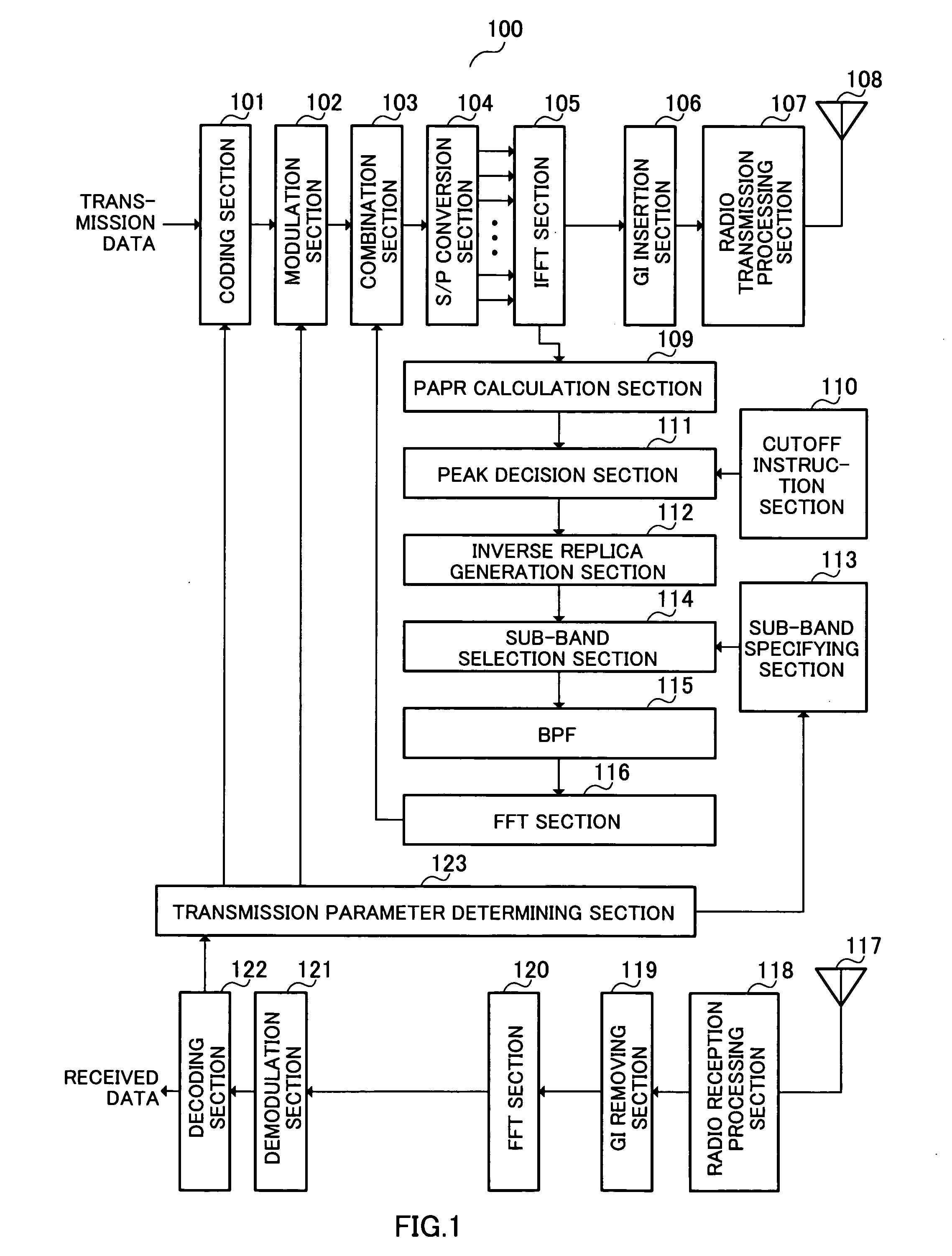
[0031]FIG. 1 is a block diagram showing the configuration of radio communication apparatus 100 according to Embodiment 1 of the present invention.
[0032] Coding section 101 codes transmission data at a coding rate from coding rate information input from transmission parameter determining section 123 and outputs the coded transmission data to modulation section 102.
[0033] Modulation section 102 modulates transmission data input from coding section 101 according to a modulation scheme based on modulation scheme information input from transmission parameter determining section 123 and outputs the modulated transmission data to combination section 103.
[0034] Based on inverse replica information, which is information about the waveform with an inverse characteristic of the waveform equal to or higher than a threshold input from FFT section 116 (hereinafter “inverse replica”), combination section 103 combines the waveform of the transmission data input from modulation section 102 and th...
embodiment 2
[0066]FIG. 12 is a flow chart showing operation of a wireless communication apparatus when suppressing peaks. The radio communication apparatus according to this embodiment 2 has the same configuration as that in FIG. 1, and therefore explanations thereof will be omitted.
[0067] Peak suppression operation by the radio communication apparatus will be explained using FIG. 12 and FIG. 13.
[0068] First, IFFT section 105 performs IFFT on transmission data (step ST1201).
[0069] Next, PAPR calculation section 109 measures PAPR (step ST1202).
[0070] Next, as shown in FIG. 4, peak decision section 111 decides whether or not there is a peak whose PAPR is equal to or higher than threshold (α) from threshold information input from cutoff instruction section 110 (step ST1203).
[0071] When there is a peak whose PAPR is equal to or higher than threshold α, sub-band selection section 114 sets K=0 (step ST1204).
[0072] Next, sub-band selection section 114 selects N (N: natural number, equal to or sm...
embodiment 3
[0081]FIG. 14 and FIG. 15 are flow charts showing peak suppression operation by a radio communication apparatus. The radio communication apparatus according to this embodiment 3 has the configuration similar to that in FIG. 1, and therefore explanations thereof will be omitted.
[0082] Peak suppression operation by the radio communication apparatus will be explained using FIG. 14.
[0083] First, IFFT section 105 performs IFFT on transmission data (step ST1401).
[0084] Next, PAPR calculation section 109 measures PAPR (step ST1402).
[0085] Next, peak decision section 111 decides whether or not there is a peak whose PAPR is equal to or higher than threshold (α) from threshold information input from cutoff instruction section 110 as shown in FIG. 4 (step ST1403).
[0086] When PAPR is equal to or higher than threshold α, FFT section 116 performs FFT on an inverse replica (step ST1404).
[0087] Next, combination section 103 combines the transmission signal and the inverse replica in a predete...
PUM
 Abstract
Description
Claims
Application Information
 - R&D
- Intellectual Property
- Life Sciences
- Materials
- Tech Scout
- Unparalleled Data Quality
- Higher Quality Content
- 60% Fewer Hallucinations
Browse by: Latest US Patents, China's latest patents, Technical Efficacy Thesaurus, Application Domain, Technology Topic, Popular Technical Reports.
© 2025 PatSnap. All rights reserved.Legal|Privacy policy|Modern Slavery Act Transparency Statement|Sitemap|About US| Contact US: help@patsnap.com


