
Delay locked loop circuit and method

a loop circuit and delay technology, applied in the direction of electrical equipment, automatic control, etc., can solve the problems of the total increase of the delay time of the vcdl, and achieve the effect of minimizing the number of phase taps, stable lock, and good performance of the dll

Active Publication Date: 2007-05-31
MOSAID TECH
View PDF31 Cites 16 Cited by
  • Summary
  • Abstract
  • Description
  • Claims
  • Application Information

AI Technical Summary

Benefits of technology

[0016] In the known art, solutions to ensure steady lock and good performance of a DLL include complicated structures such as dual-loop structures. Multiphase versions of the clock signal or clock inversion in the simplest case are also used. However they are used in order to minimize number of phase taps in the VCDL and / or provide a delay line with a smaller number of stages. The phase taps in turn are used to increase flexibility in synchronization of pipeline stages, but not for the purposes of achieving steady lock and stable performance of the DLL itself.
[0017] Typically, designers of DLLs are reluctant to spend much time dealing with such a “secondary” issue as initialization and they rely on traditional “proven” approaches. Therefore, it is desirable to provide a DLL initialization method that mitigates the problems of conventional approaches.
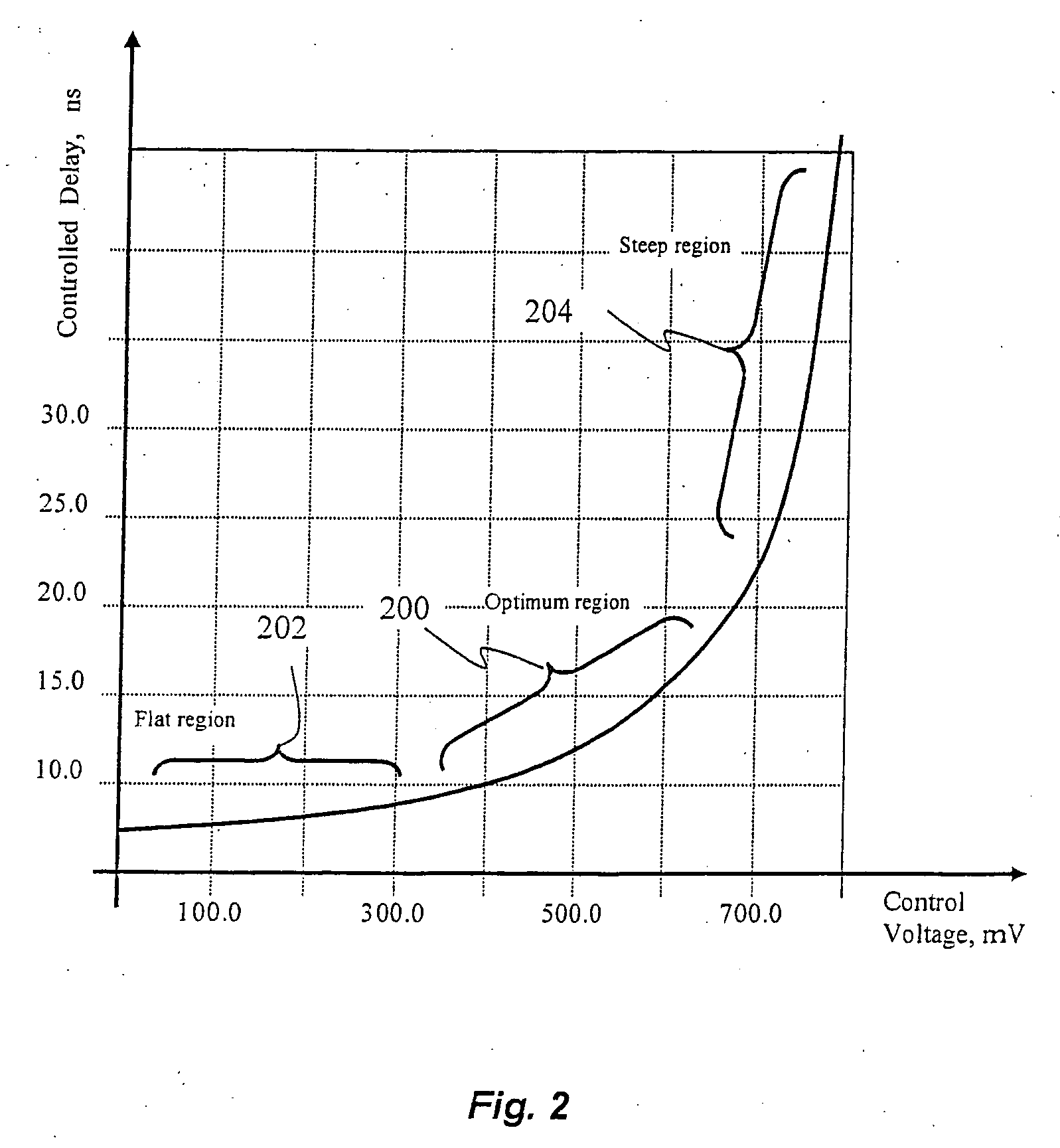
[0018] We present a method and apparatus for ensuring that a DLL is initialized to the correct operating point, not too close to either end of a delay vs. control voltage characteristic. Initialization circuitry forces the DLL to search for a lock point always starting from an initial delay corresponding to one end of the delay vs. voltage characteristic, and allowing the DLL to only vary the controlled delay in one direction until the final lock is reached. After the final lock is reached, the DLL can increase or decrease the controlled delay as needed, to dynamically maintain the lock point. According to the method offered by the present invention, the DLL is also forced to skip the first lock point and the process of skipping is made easier and faster by shifting the phase of a DLL internal clock signal.

Problems solved by technology

The phase taps in turn are used to increase flexibility in synchronization of pipeline stages, but not for the purposes of achieving steady lock and stable performance of the DLL itself.
This results in a total increase of VCDL delay time about equal to the duration of one entire clock period.

Method used


Image

  • Delay locked loop circuit and method
  • Delay locked loop circuit and method
  • Delay locked loop circuit and method

Examples


Embodiment Construction

[0040] A description of preferred embodiments of the invention follows.

[0041] In the following description, numerous specific details are set forth to provide a thorough understanding of the invention. However, it is understood that the invention may be practiced without these specific details. In other instances, well-known structures or and / or processes have not been described or shown in detail in order not to obscure the invention. In the description and drawings, like numerals refer to like structures or processes. Generally, operation of a Delay Locked Loop (DLL) is well known in the art and will not be described further except where necessary to clarify aspects of the invention.

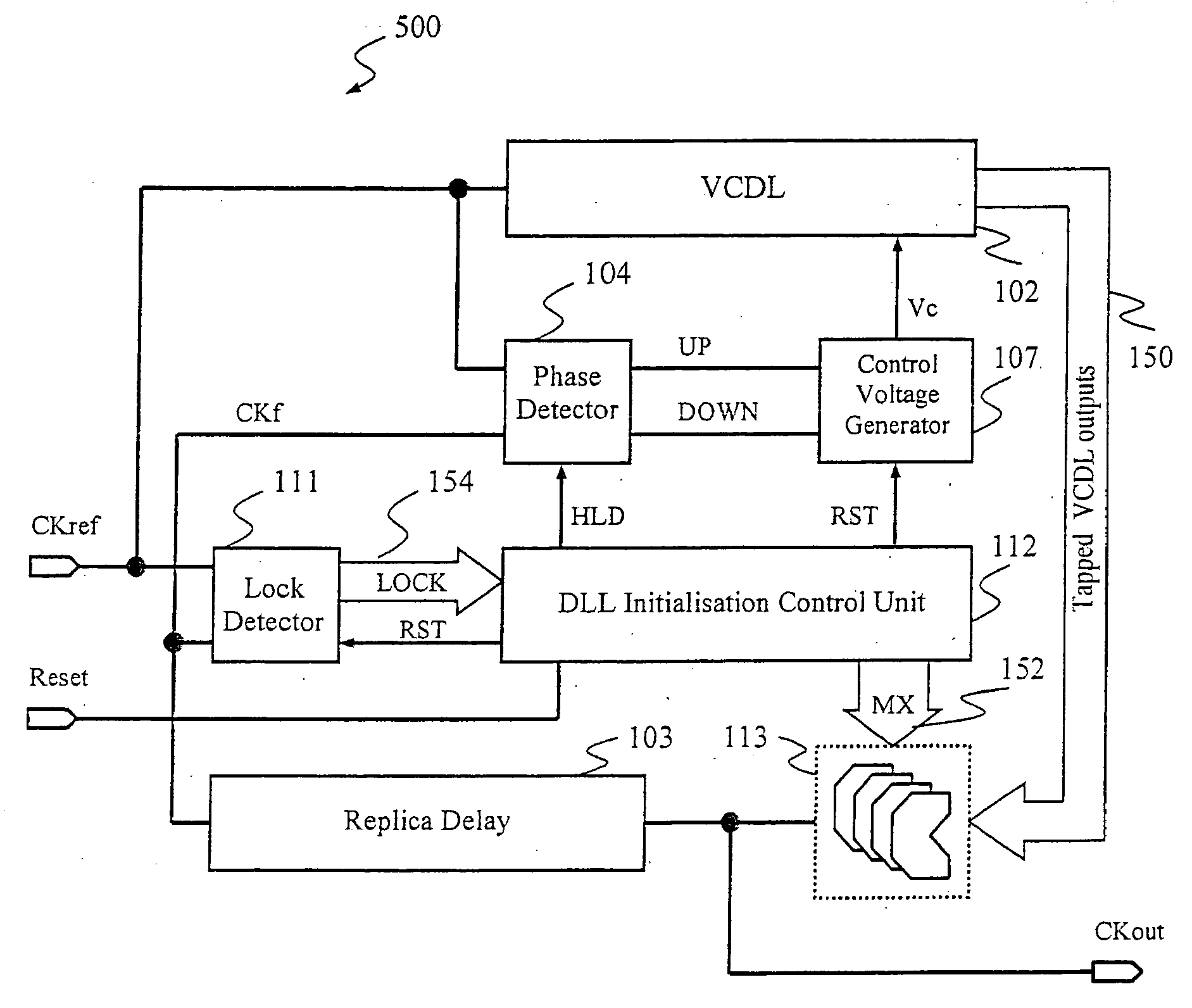
[0042]FIG. 5 is a block diagram of an embodiment of a Delay Lock Loop (DLL) 500 that includes a DLL Initialization control 112 for initializing the DLL 500 after power-up or reset according to the principles of the present invention. The DLL 500 includes a Voltage Controlled Delay Line (VCDL) 102, Ph...


PUM


Abstract

A delay locked loop includes initialization circuitry that ensures that a DLL is initialized to an operating point that is not to close to either end of a delay vs. control voltage characteristic. The initialization circuitry forces the DLL to initially search for a lock point starting from an initial delay, the delay is varied in one direction, forcing the DLL to skip the first lock point. The initialization circuitry only allows the DLL to vary the delay of the voltage controlled delay loop in the one direction from the initial delay until the operating point is reached.

Description

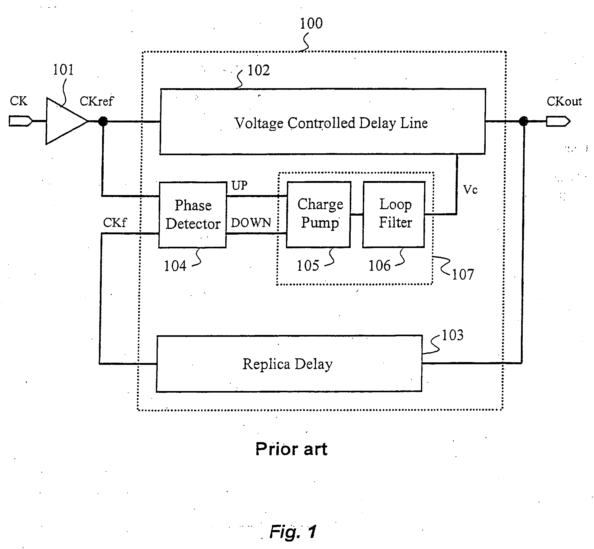
RELATED APPLICATION [0001] This application is a continuation of U.S. application Ser. No. 11 / 050,644, filed Feb. 3, 2005. The entire teachings of the above application are incorporated herein by reference.BACKGROUND OF THE INVENTION [0002]FIG. 1 is a block diagram of a prior art conventional Delay Locked Loop (DLL) 100. The main function of a DLL is to synchronize two clock signals by aligning their rising edges. An externally supplied clock signal CK is buffered by clock buffer 101 to provide a reference clock signal CKref that is coupled to a voltage controlled delay line (VCDL) 102 and a phase detector (PD) 104. The voltage controlled delay line 102 produces a DLL output clock signal CKout, which is a delayed version of CKref and is routed to various circuits within a device through a buffering structure referred to as a clock tree. [0003] A feedback clock signal CKf is tapped at a terminal node of a branch of the clock tree or obtained by applying the output clock signal CKout ...

Claims


Application Information

Patent Timeline
Patent Type & Authority Applications(United States)
IPC IPC(8): H03L7/06
CPCH03L7/0812H03L7/0891H03L7/08H03L7/095H03L7/10H03L7/0895H03L7/0816H03L7/06
Inventor HAERLE, DIETERMAI, TONYVLASENKO, PETER
Owner MOSAID TECH
Learn More