
Resonant vibratory device having high quality factor and methods of fabricating same

a vibratory device and high quality factor technology, applied in the direction of resonant frequency, acceleration measurement using interia force, instruments, etc., can solve the problems of large size/volume of such devices, disadvantageous size and power consumption of devices, and unsuitability of resonant devices previously accepted as satisfactory

Inactive Publication Date: 2007-05-31
CALIFORNIA INST OF TECH
View PDF4 Cites 60 Cited by
  • Summary
  • Abstract
  • Description
  • Claims
  • Application Information

AI Technical Summary

Benefits of technology

[0008] In one aspect, the invention relates to a resonant vibratory sensor having an output signal proportional to a thermoelastic quality factor, QTE, wherein QTE is given by: QTE=Qo[1+(ω⁢ ⁢τ)22⁢(ω⁢ ⁢τ)]whereQo=2⁢CvE⁢ ⁢α2⁢To

Problems solved by technology

In recent years, however, the demands of such industries have shifted or increased, and, in turn, characteristics and / or performance levels of resonant devices that were previously accepted as satisfactory have become unsuitable.
Over time, it became clear that such devices tended to be disadvantageously large and power consumptive and / or suffered from issues relating to dead-band non-linearities and / or light source life.
The large size / volume of such devices became a particular problem, since industries in which they were being used, especially the military and transportation industries, were increasingly seeking to incorporate such devices in miniature and / or portable platforms.
Unfortunately, however, MEMS-based resonant devices were not without their shortcomings.
Most notably, it was observed that some of such devices suffered from comparatively lower performance than non-MEMS-based counterparts.

Method used


Image

  • Resonant vibratory device having high quality factor and methods of fabricating same
  • Resonant vibratory device having high quality factor and methods of fabricating same
  • Resonant vibratory device having high quality factor and methods of fabricating same

Examples


Embodiment Construction

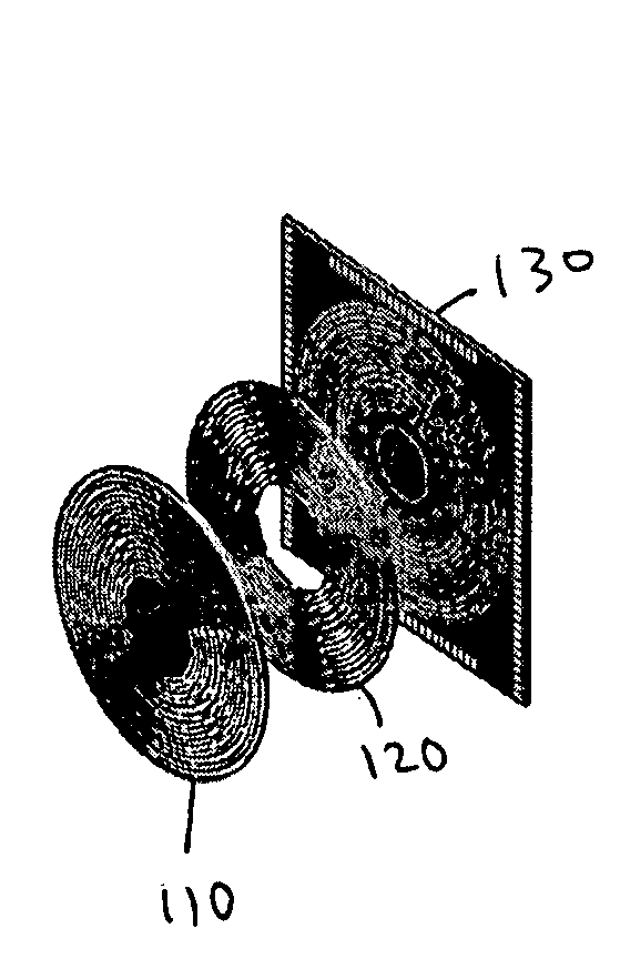
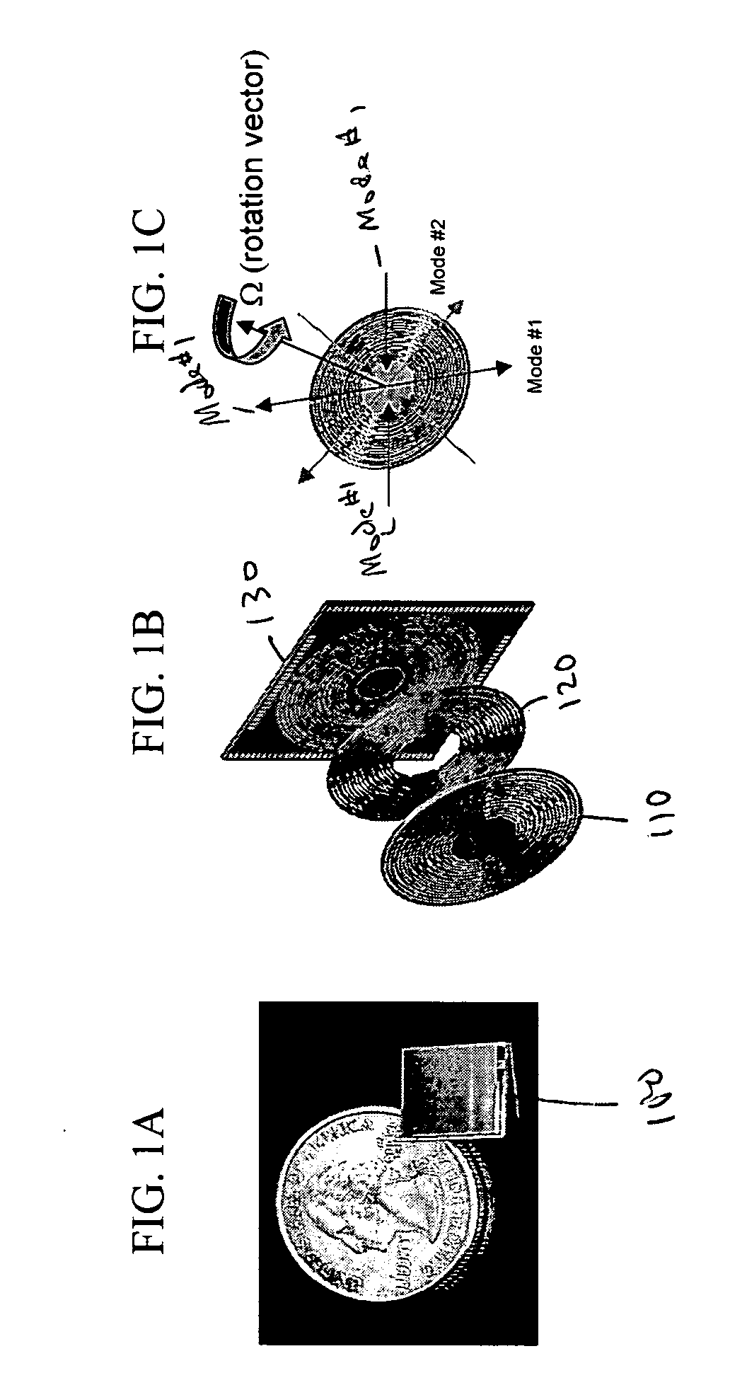
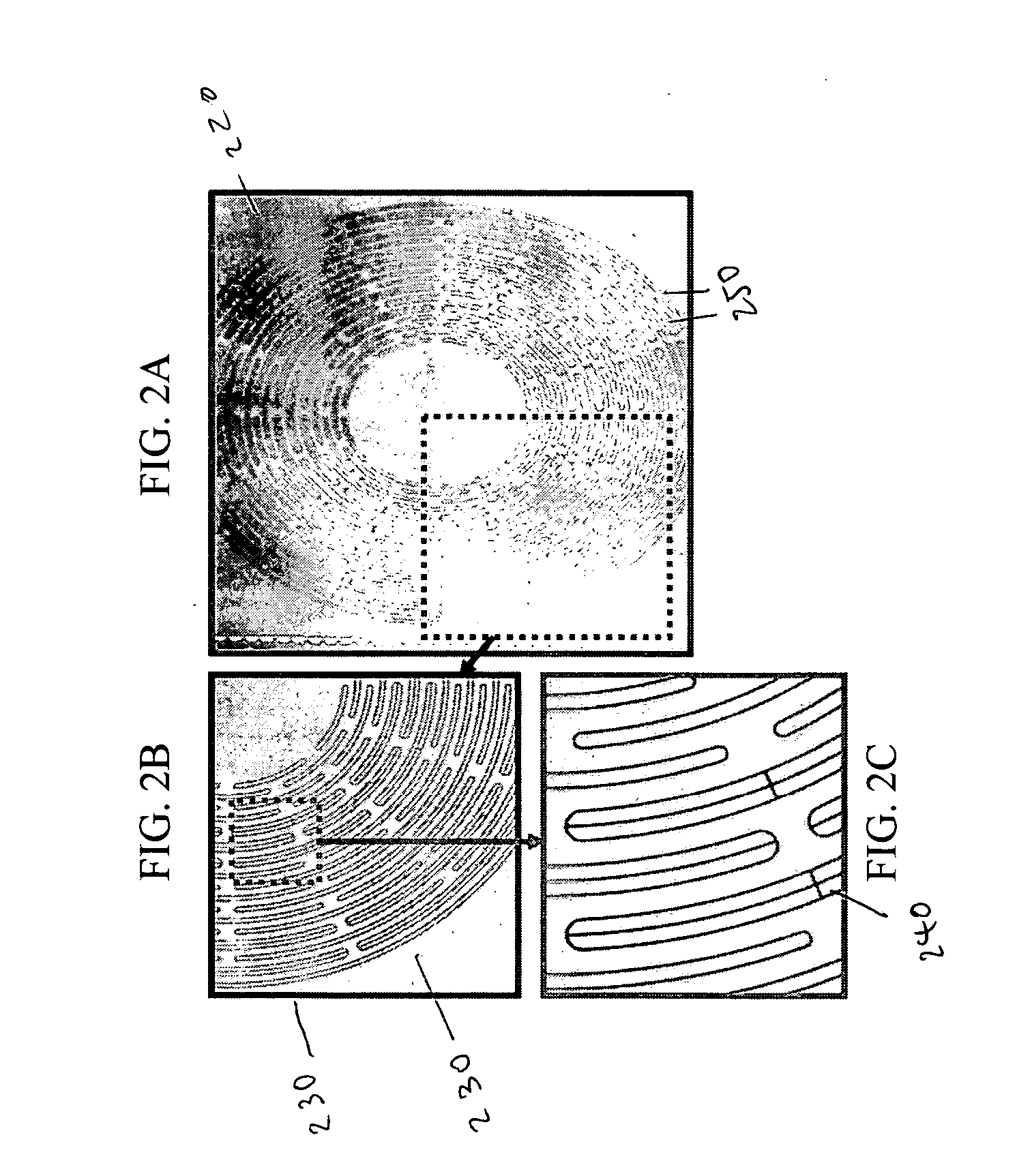
[0027] The present application discloses resonant vibratory sensors, which, by virtue of being formed from material exhibiting an ultra low coefficient of expansion (e.g., titania silicate glass) are believed to provide an unprecedented combination of small size / volume, low power consumption, high precision and high performance. The approach is expected to provide an improvement in performance (i.e. bias stability and ARW) that is expected to be of the order of one thousand-fold improvement over existing commercial MEMS devices. Reduction of mass, volume and power over comparable performance optical gyros is projected to be of the order of a factor of one hundred (100). Based on modeled data, it is further believed that resonant vibratory sensors made from such a material would be better suited than conventional MEMS-based resonant vibratory sensors for many important uses, including as portable, navigation-grade, inertial measurement units (IMUs) for applications that include targe...


PUM


Abstract

The invention provides resonant vibratory sensors to render such resonant vibratory sensors more beneficial than conventional MEMS-based and non-MEMS-based resonant vibratory sensors for various usage applications, such as portable applications requiring navigation-grade performance. The resonant vibratory sensors include as examples an oscillator, a vibratory gyroscope and a vibratory accelerometer. In one embodiment, the resonant vibratory sensor is a disk resonator gyroscope. The improved resonant vibratory sensors employ materials having an ultra low thermal expansion coefficient, which provides an improved thermoelastic quality factor.

Description

CROSS-REFERENCE TO RELATED APPLICATIONS [0001] This application claims priority to and the benefit of co-pending U.S. provisional patent application Ser. No. 60 / 736,955, filed Nov. 15, 2005, which application is incorporated herein by reference in its entirety.STATEMENT REGARDING FEDERALLY FUNDED RESEARCH OR DEVELOPMENT [0002] The invention described herein was made in the performance of work under a NASA contract number NASA-1407, and is subject to the provisions of Public Law 96-517 (35 U.S.C. §202) in which the Contractor has elected to retain title.FIELD OF THE INVENTION [0003] The invention relates to vibratory devices in general and particularly to resonant vibratory devices having an improved quality factor compared to conventional devices. BACKGROUND OF THE INVENTION [0004] Resonant devices, such as resonant vibratory devices and sensors, have long served various technical functions in many important industries. For example, in past decades resonant devices such as oscillato...

Claims


Application Information

Patent Timeline
Patent Type & Authority Applications(United States)
IPC IPC(8): G01H17/00G01P15/097G01P9/04
CPCG01C19/5684G01H13/00G01P15/097
Inventor YEE, KARL Y.
Owner CALIFORNIA INST OF TECH
Learn More