
Printable laminate, printable laminate kit and method for producing the same

a technology of printable laminate and laminate kit, which is applied in the field of printing laminate, can solve the problems of printer damage, all or part of the removable element being separated from the waste element,

Inactive Publication Date: 2007-05-24
MORRISH PETER GEOFFREY ALAN +4
View PDF9 Cites 43 Cited by
  • Summary
  • Abstract
  • Description
  • Claims
  • Application Information

AI Technical Summary

Benefits of technology

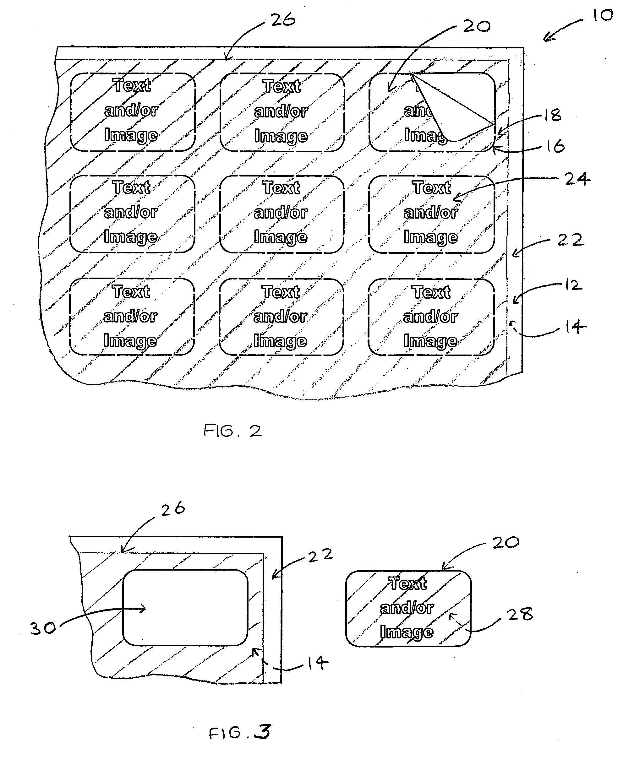
[0005] One approach considered by the present inventor has been to provide a printable laminate of a top sheet and a backing sheet, the top sheet being cut to define a plurality of removable elements and a waste element. In use, the top sheet is printable, so that the removable elements (and also the waste element, if desired) are printed. After printing, the removable elements can be removed and used to customise an item, or to produce a novelty item or a stationery item. The advantage of this approach is that a small number of removable elements can be printed (e.g. one sheet of the printable laminate) using a conventional printing apparatus, such as a photocopier or a printer controlled by computer.
[0059] Preferably, the printing step prints at least part of the customising image onto the waste element. In this way, it can be ensured that the image extends substantially to the perimeter of the removable shaped element. The printing step is preferably carried out using readily-available printing equipment such as an ink-jet or laser printer, or a photocopier.

Problems solved by technology

However, it has been found that such printable laminates suffer from a problem that all or part of a removable element has a tendency to separate from the waste element when the printable laminated is printed.
This problem is particularly noticeable when the printable laminate is guided around rollers in the printing apparatus.
The result can be detachment of one or more removable elements during printing, with corresponding damage to the printer.

Method used


Image

  • Printable laminate, printable laminate kit and method for producing the same
  • Printable laminate, printable laminate kit and method for producing the same
  • Printable laminate, printable laminate kit and method for producing the same

Examples


Embodiment Construction

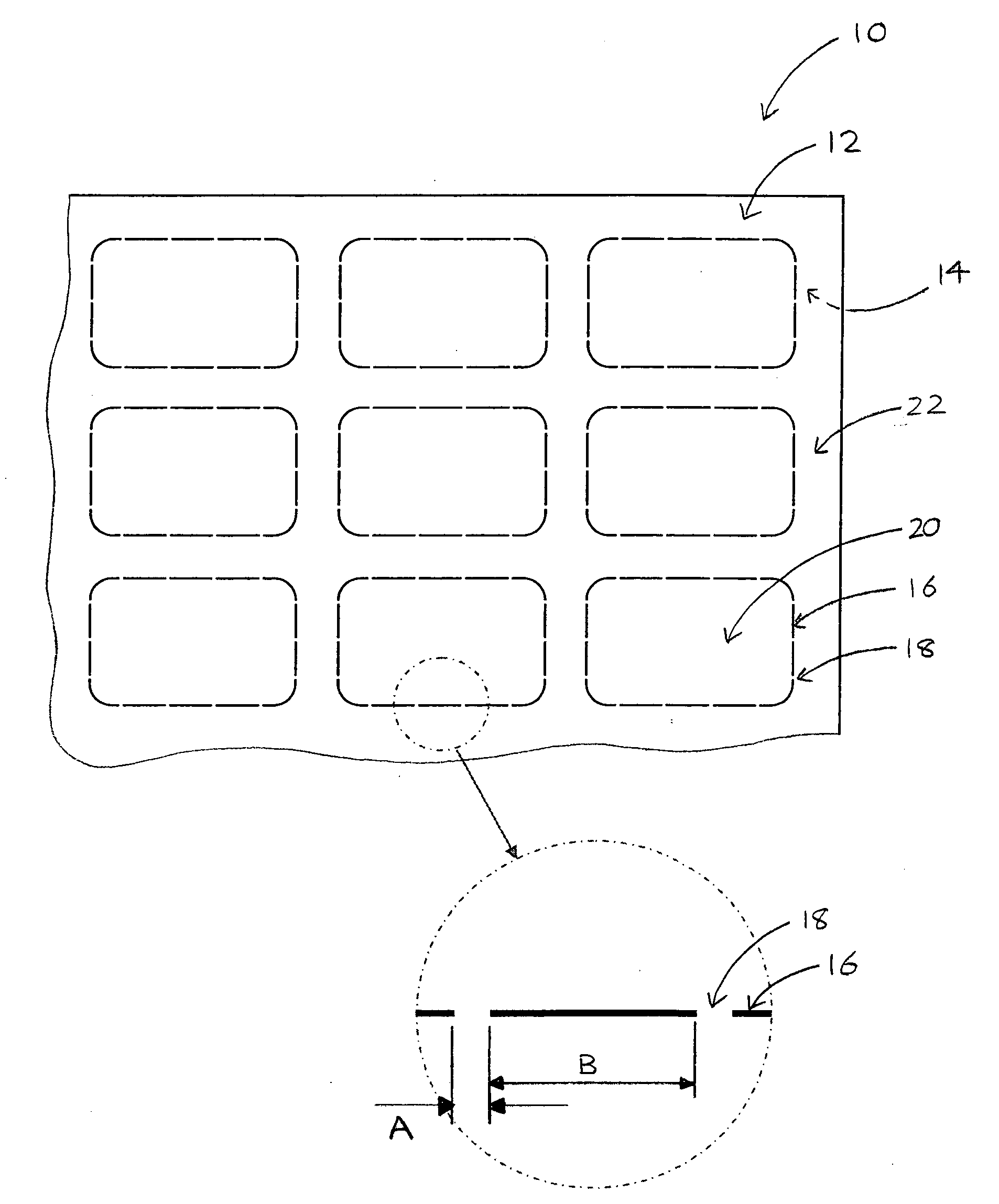
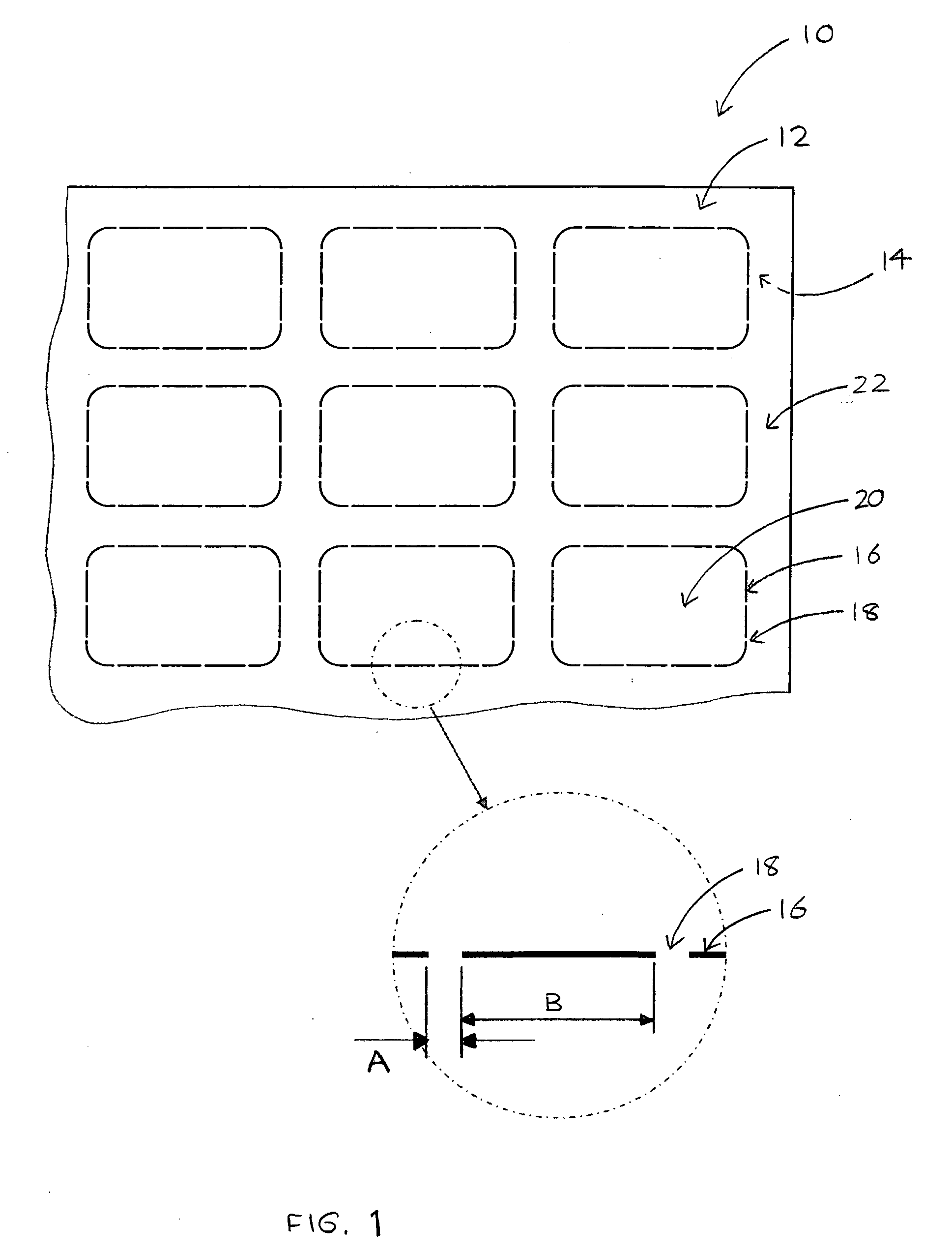
[0081] The printable laminate 10 in the embodiments shown in FIGS. 1 to 13 is formed from a “dry-peel” laminate, such as a known dry-peel laminate from companies such as Avery™, or other stationery supply companies. The printable laminate 10 comprises a top sheet 12 bonded with a backing sheet 14, which may be separated, or peeled, apart so that the exposed surfaces of both the top sheet 12 and backing sheet 14 are substantially non-adhesive, or not sticky or tacky to the touch. In some embodiments, the backing sheet may be adhesive after peeling, but the top sheet is preferably not adhesive after peeling.

[0082] The printable laminate 10 is preferably a standard ISO paper size, such as A4 (210 mm×297 mm) or other standard paper size, such as US letter size (8.5″×11″). This allows the printing operation to be carried out on readily-available printing equipment such as a laser or ink-jet printer, or a photocopier.

[0083] The top sheet 12 of the printable laminate 10 is typically a pa...


PUM


Abstract

A printable laminate, kit and methods for making and modifying the same, the printable laminate comprising a top sheet laminated with a backing sheet. The top sheet is printable and cut by at least one intermittent cut line to define a corresponding number of removable elements, and a waste element. The intermittent cut line includes a plurality of bridging portions which connect the, or each, removable element to the waste element. Removal of a removable element from the backing sheet and waste element is typically achieved by lifting of a side or corner of the removable element and breaking the bridging portions in series along the intermittent cut line.

Description

BACKGROUND TO THE INVENTION [0001] The present invention relates to printable laminates. More particularly, but not exclusively, it relates to printable laminates comprising removable elements. Such removable elements may be used as an insert element to customise an item, such as a drinks coaster, key fob, name tag or the like, by insertion into a pocket within that item such that text and / or an image printed on the insert element is visible through a transparent portion of the item. Alternatively, the removable elements may be used to form three-dimensional novelty items such as hats, containers, or the like by folding or other means. As a further alternative, the removable elements may be used as stationery items such as tickets, greetings cards, place cards or the like, or for insertion into stationery articles such as calendars, notebooks, diaries or the like. [0002] It may often be desirable to produce relatively small numbers of an element for use as a novelty item, stationery...

Claims


Application Information

Patent Timeline
Patent Type & Authority Applications(United States)
IPC IPC(8): B42D15/00
CPCB32B7/06B42D5/04B42D15/0053B42P2241/22G09F3/0288G09F3/10G09F3/02B32B38/0004B32B2307/75
Inventor MORRISH, JOHN
Owner MORRISH PETER GEOFFREY ALAN
Learn More