
Wireless communication system for pressure monitoring

a communication system and wireless technology, applied in the field of wireless communication system for pressure monitoring, can solve the problems of cumbersome cable connection of transducer to vital signs monitor, inability to monitor blood pressure for longer term, and inability to accurately estimate the accuracy of methods by as much as 10 percent, so as to reduce the number of errors introduced

Inactive Publication Date: 2007-05-17
EDWARDS LIFESCIENCES LLC
View PDF99 Cites 55 Cited by
  • Summary
  • Abstract
  • Description
  • Claims
  • Application Information

AI Technical Summary

Benefits of technology

[0013] It is another object of the present invention to provide a wireless communication system that can function with most pressure transducer systems currently used in hospitals.
[0014] It is another object of the present invention to provide a wireless communication system that reduces errors introduced by electrical signal measurement and reproduction.

Problems solved by technology

While indirect methods of blood pressure monitoring, such as with a pressure cuff and stethoscope, are often desired for quick pressure readings, these methods can be inaccurate by as much as 10 percent, making them undesirable for longer term blood pressure monitoring of more critical patients.
One disadvantage to these systems is the cumbersome cable connecting the transducer to the vital signs monitor.
These cords can easily tangle, can accidentally pull out from the vital signs monitor, and can be easily confused when multiple pressure monitoring lines are used.
Further, the length of these cords limits the distance the patient can move from the vital signs monitor and must be disconnected and secured when a patient is transported within the hospital.
In this respect, the current wireless transducer systems cannot connect to standard transducers or standard vital signs monitors.
Since vital signs monitors are integrated with hospital information systems and represent a significant expense, hospitals are reluctant to switch to these wireless systems which would require the use of only that company's transducer system equipment.
However, unlike invasive blood pressure, ECG does not utilize an artificial transducer or an excitation voltage.

Method used


Image

  • Wireless communication system for pressure monitoring
  • Wireless communication system for pressure monitoring
  • Wireless communication system for pressure monitoring

Examples


Embodiment Construction

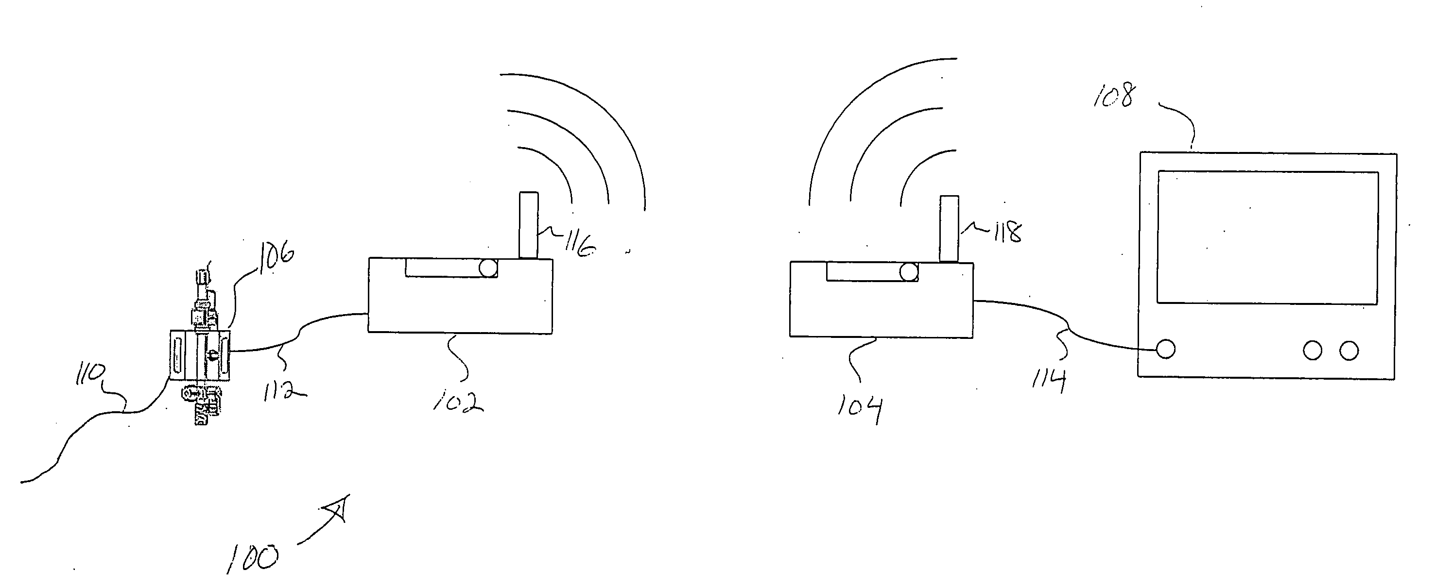
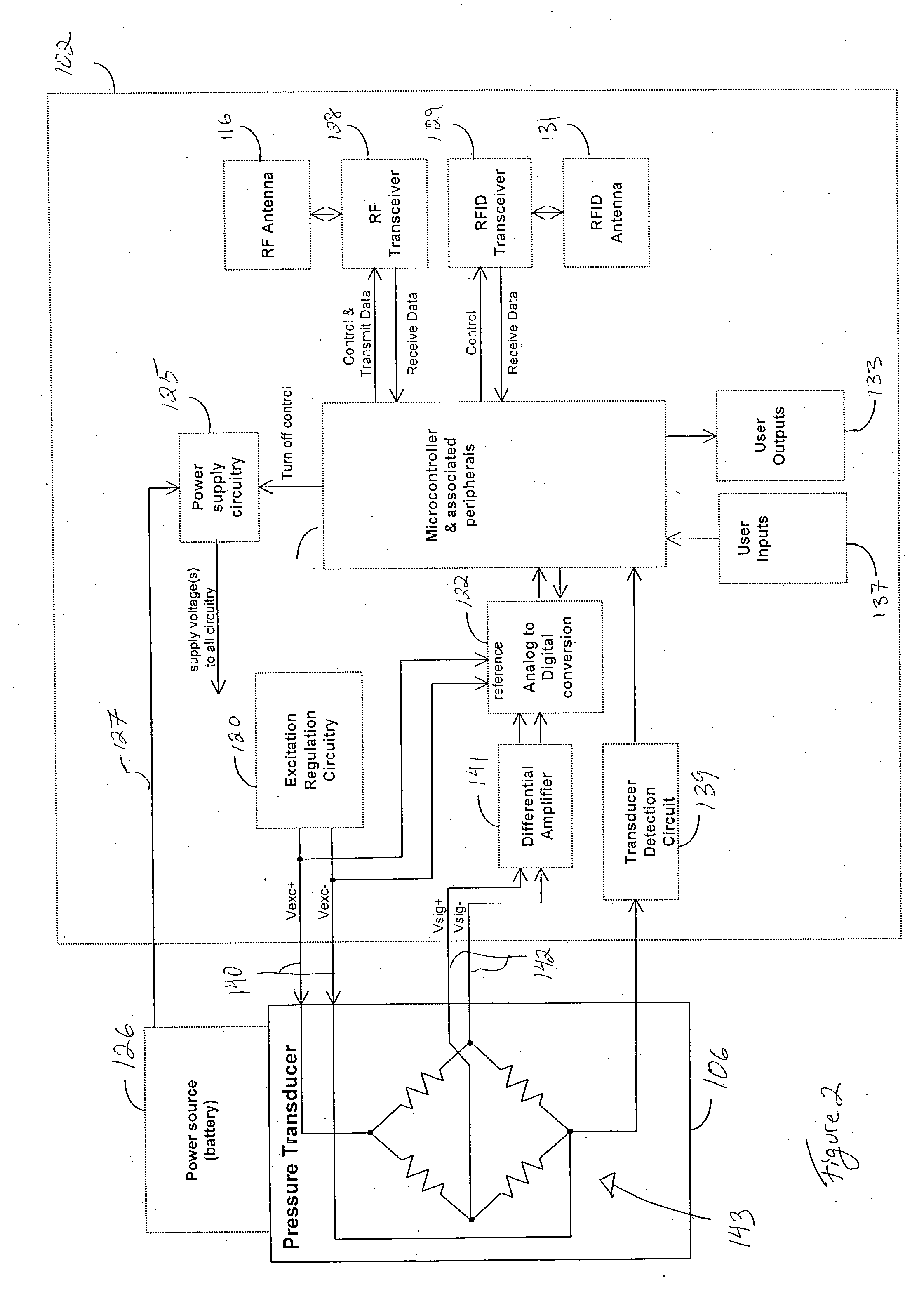
[0028]FIG. 1 illustrates a preferred embodiment of a wireless pressure system 100 according to the present invention that can communicate data between a standard pressure transducer 106 (e.g. compliant with the previously described BP22 standard) and a standard vital signs monitor 108 (e.g. compliant with the previously described BP22 standard). More specifically, the wireless pressure system 100 includes a portable unit 102 that provides an excitation voltage to the transducer 106 to receive an output voltage that is proportional to the pressure of a catheter 110. The portable unit 102 digitizes this pressure data, then transmits that data to a monitor interface unit 104 which emulates a corresponding output voltage to the vital signs monitor 108. Consequently, the vital signs monitor 108 receives and displays a signal from the monitor interface unit 104 which corresponds to the actual pressure measured by the portable unit 102, allowing the user to connect and therefore make use o...


PUM


Abstract

In one embodiment, the present invention provides a wireless communication system for use with a blood pressure monitor system. The wireless communication system includes a portable unit that connects to a typical pressure transducer and a monitor interface unit that connects to a typical vital signs monitor. The portable unit obtains a pressure reading from the transducer by providing an excitation voltage to the transducer, then wirelessly transmitting the pressure data to the monitor interface unit. The monitor interface unit measures the excitation voltage supplied by the vital signs monitor to supply the pressure reading in a format recognizable by the vital signs monitor.

Description

RELATED APPLICATIONS [0001] This application claims priority to U.S. Provisional Application Ser. No. 60 / 736,428, filed Nov. 14, 2005 entitled Wireless Communication System For Pressure Monitoring; and U.S. Provisional Application Ser. No. 60 / 736,408, filed Nov. 14, 2005 entitled Wireless Communication Protocol For A Medical Sensor System, and are hereby incorporated by reference.BACKGROUND OF THE INVENTION [0002] The measurement of blood pressure is an important technique used by medical personnel for diagnosing and treating a wide range of injuries and conditions. By measuring and especially monitoring a patient's blood pressure, medical personnel can be alerted to problems at an early stage, increasing the likelihood of successful treatment. [0003] While indirect methods of blood pressure monitoring, such as with a pressure cuff and stethoscope, are often desired for quick pressure readings, these methods can be inaccurate by as much as 10 percent, making them undesirable for lon...

Claims


Application Information

Patent Timeline
Patent Type & Authority Applications(United States)
IPC IPC(8): A61B5/02
CPCA61B5/0002A61B5/0215A61B5/03A61B2560/0271A61B2560/045
Inventor HEITZMANN, HAROLD A.MOONEY, CHARLES R.YADLOWSKY, ANN B.
Owner EDWARDS LIFESCIENCES LLC
Learn More