
Method and system for reducing channel interference in a frame-synchronized wireless communication system

a wireless communication system and channel interference technology, applied in the field of communication systems, can solve the problems of not allowing frame synchronization between base stations, not allowing coordination between base stations, and frequency re-use cannot be used as aggressively as can be used in bwa systems, so as to reduce channel interference, reduce co-channel interference, and reduce co-channel interference

Inactive Publication Date: 2007-05-17
WI LAN INC
View PDF39 Cites 10 Cited by
  • Summary
  • Abstract
  • Description
  • Claims
  • Application Information

AI Technical Summary

Benefits of technology

This approach enhances the C / I ratio, increases system capacity, and improves spectrum efficiency by optimizing uplink and downlink bandwidth allocation, allowing for more aggressive frequency reuse and efficient data transmission.

Problems solved by technology

Therefore, these systems do not allow for frame synchronization between base stations and disadvantageously do not permit coordination between the base stations for purposes of reducing co-channel interference.
Wireless communication systems rely upon frequency re-use because frequency allocation or bandwidth is typically limited.
Due to the nature of the systems described in the incorporated U.S. Pat. No. 6,038,455, and in PCS, cellular and paging systems of the prior art, frequency re-use cannot be used as aggressively as it can be used in BWA systems.
Similarly, the base station can receive unwanted RF energy from terminal stations.
Receiving unwanted RF energy causes channel interference in the form of co-channel interference or adjacent channel interference.

Method used


Image

  • Method and system for reducing channel interference in a frame-synchronized wireless communication system
  • Method and system for reducing channel interference in a frame-synchronized wireless communication system
  • Method and system for reducing channel interference in a frame-synchronized wireless communication system

Examples


Embodiment Construction

[0032] Throughout this description, the embodiments and examples shown should be considered as exemplars, rather than as limitations.

[0033] An exemplary broadband wireless communication system for use with the embodiments described herein is described in the related U.S. Pat. No. 6,016,311, by Gilbert et al., issued Jan. 18, 2000, entitled “Adaptive Time Division Duplexing Method and System for Dynamic Bandwidth Allocation within a Wireless Communication System”, which is hereby incorporated by reference. The communication system described in U.S. Pat. No. 6,016,311 is an adaptive time division duplexing (ATDD) method and system for duplexing transmissions in wireless communication systems. The ATDD system adapts to the uplink and downlink bandwidth requirements of the channels.

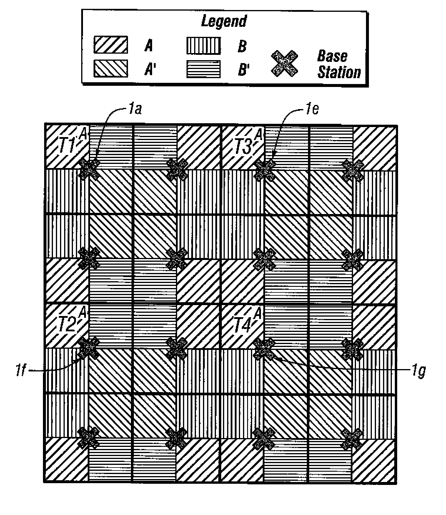
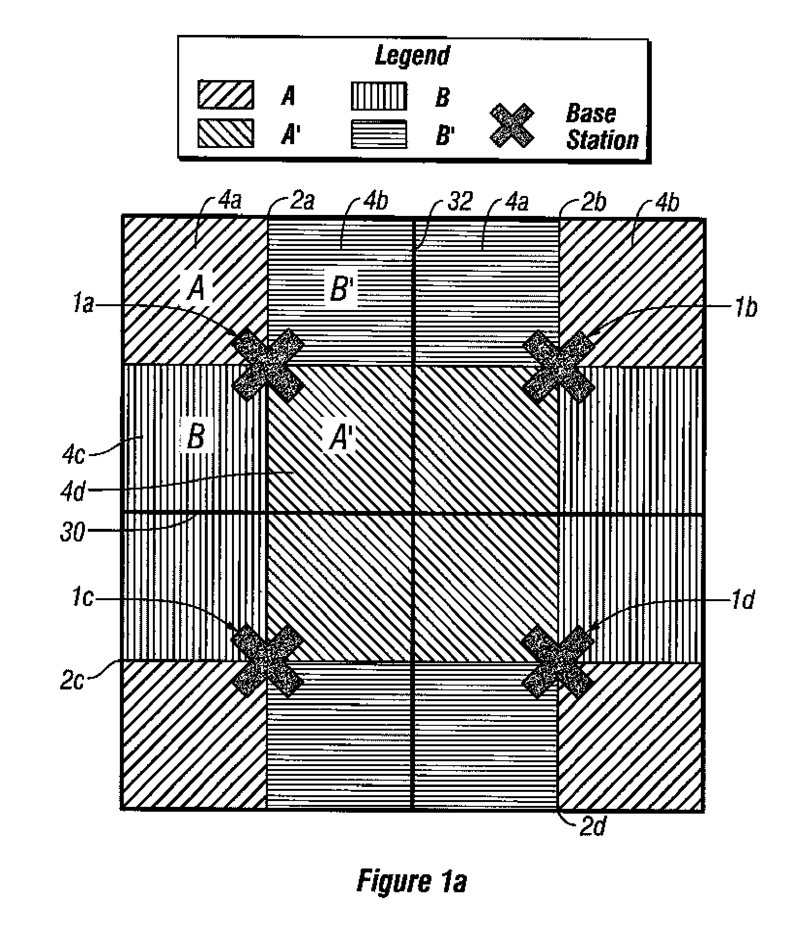
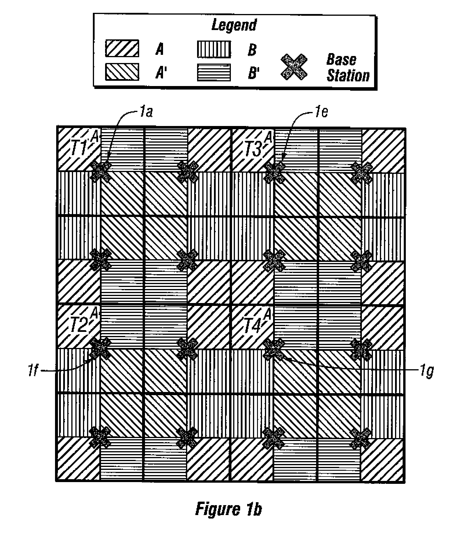
[0034]FIG. 1a is a diagram of a wireless communication system configuration incorporating frequency reuse where a plurality of base stations 1(a)-(d) communicate with fixed terminal stations (i.e., “subscri...


PUM


Abstract

Base stations having potentially interfering terminal stations that are geographically located on the same or similar diagonal or Line of Sight (relative to the base station) operate on a first set of time frames (e.g., “even” time frames). Similarly, base stations having potentially interfering terminal stations that are not geographically located on the same or similar diagonals operate on a second set of time frames (e.g., “odd” time frames). By alternating in their use of the even and odd frames, the potential for co-channel interference between terminal stations is minimized. Systems and methods are disclosed which reduce co-channel and adjacent channel interference between terminal stations of different cells as well as adjacent channel interference between terminal stations of adjacent cells. The methods and systems so described can be used during the deployment or expansion of a communication system in a region.

Description

RELATED APPLICATIONS [0001] This application claims priority to provisional application Ser. Nos. 60 / 248,867, filed Nov. 15, 2000, titled “METHOD AND APPARATUS FOR REDUCING CO-CHANNEL INTERFERENCE IN A FRAME-SYNCHRONIZED WIRELESS COMMUNICATION SYSTEM” and 60 / 249,769, filed Nov. 16, 2000, titled “METHOD AND APPARATUS FOR REDUCING CO-CHANNEL INTERFERENCE IN A FRAME-SYNCHRONIZED WIRELESS COMMUNICATION SYSTEM,” both of which are hereby incorporated by reference.BACKGROUND OF THE INVENTION [0002] 1. Field of the Invention [0003] This invention relates to communication systems and to a method and system for reducing channel interference in a wireless communication system. [0004] 2. Description of Related Art [0005] A wireless communication system facilitates two-way communication between a plurality of subscriber radio stations or subscriber units (either fixed or portable) and a fixed network infrastructure. Exemplary systems include mobile cellular telephone systems, personal communicat...

Claims


Application Information

Patent Timeline
Patent Type & Authority Applications(United States)
IPC IPC(8): H04B1/00H04B15/00H04W16/02H04W16/12H04W16/24
CPCH04W16/02H04W16/12H04W16/24
Inventor KLEIN, ISRAEL JAYGILBERT, SHELDEN L.STANWOOD, KENNETH L.BEHAR, JACQUES
Owner WI LAN INC
Learn More