
Clip type light detachably coupled with cap

a light emitter and clip technology, applied in the field of clip light emitters, can solve the problems of ensuring the user's vision field and affecting the activity of users, and achieve the effect of preventing the lamp from moving or separating, and being easy to attach or detachabl

Active Publication Date: 2007-05-17
SOHN
View PDF30 Cites 28 Cited by
  • Summary
  • Abstract
  • Description
  • Claims
  • Application Information

AI Technical Summary

Benefits of technology

[0010] An object of the present invention is to provide a clip type light, which is easily attached or detached from a cap visor while keeping an external appearance of the cap visor regardless of the various curved configurations of the cap visor, without causing damage to an outer skin of the cap visor, while preventing the lamp from moving or separating from the cap visor even if the user is involved in intensive activities.
[0011] The clip type light may include a switch, which is provided at a lower portion of a body of the clip type light so as to operate an electric lamp and an ultrasonic wave generator (e.g., ultrasonic insect repellent) in such a manner that the user can easily operate the electric lamp and the ultrasonic wave generator while wearing the cap equipped with the clip type light.
[0012] The ultrasonic generator may be provided at a lower portion of the clip type light in order to generate ultrasonic waves to prevent insects from gathering in the vicinity of the electric lamp of the clip type light.

Problems solved by technology

Although the cap does not cause special problems when the user is engaged in daytime activities, such a cap does not ensure the user's field of vision at night, so the user must carry a light source (e.g. a flashlight).
In addition, since the user must move while gripping the light source when the user is engaged in night activities, the activity of the user may become impeded.
Further, since the user must move along the path illuminated by the light, the user may be careless of peripheral environment, resulting in an accident.
Accordingly, the worker has to perform the work singlehandedly, causing inconvenience.

Method used


Image

  • Clip type light detachably coupled with cap
  • Clip type light detachably coupled with cap
  • Clip type light detachably coupled with cap

Examples


first embodiment

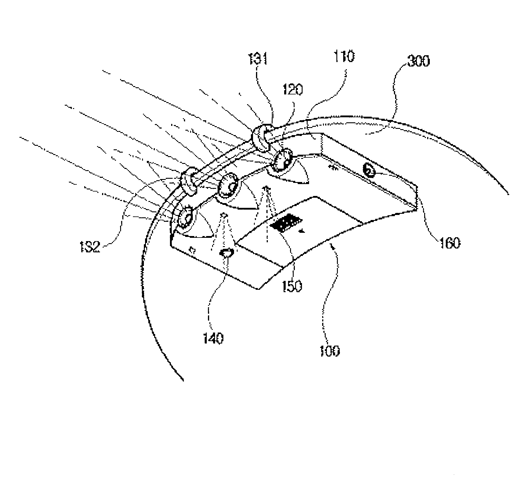
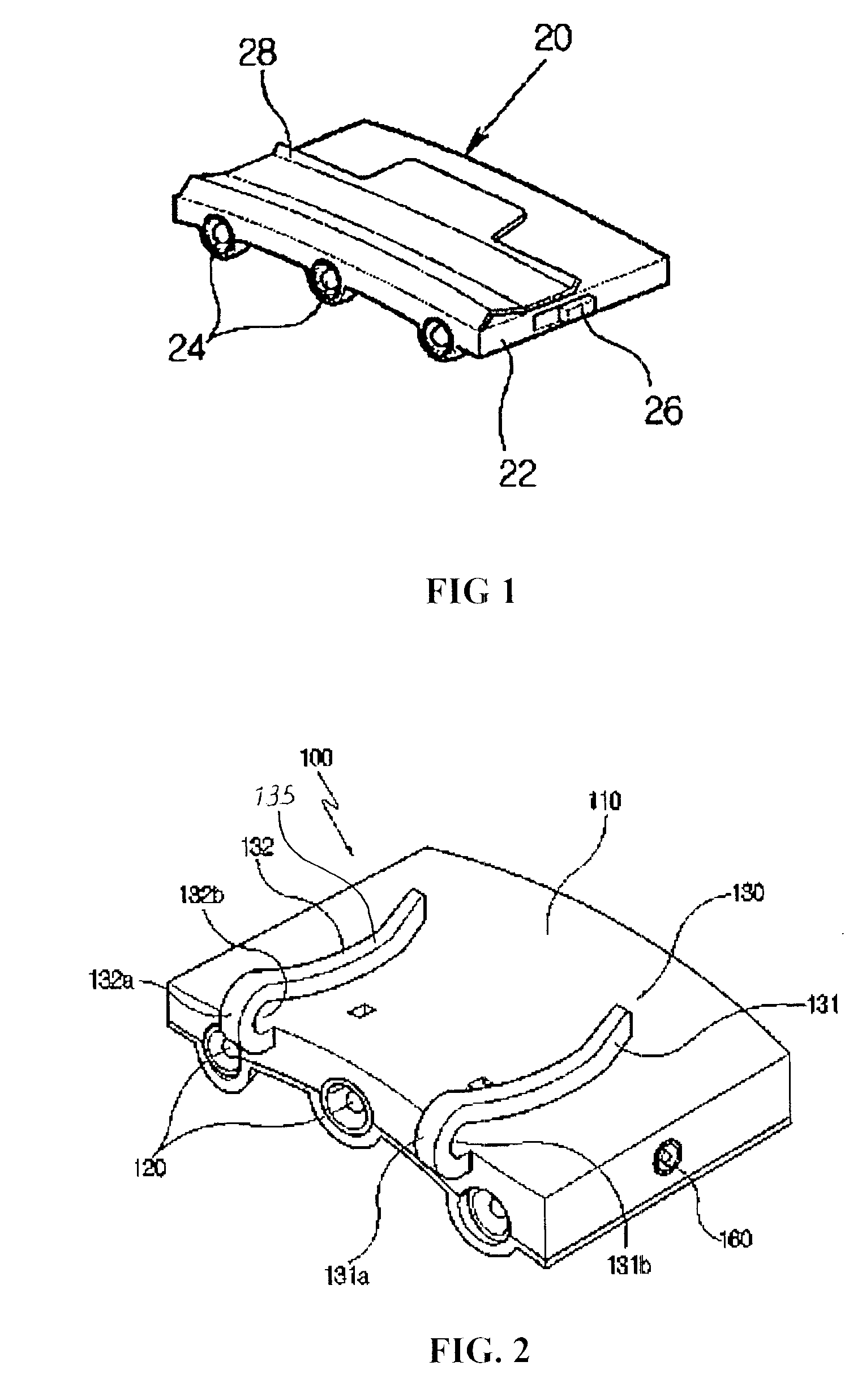
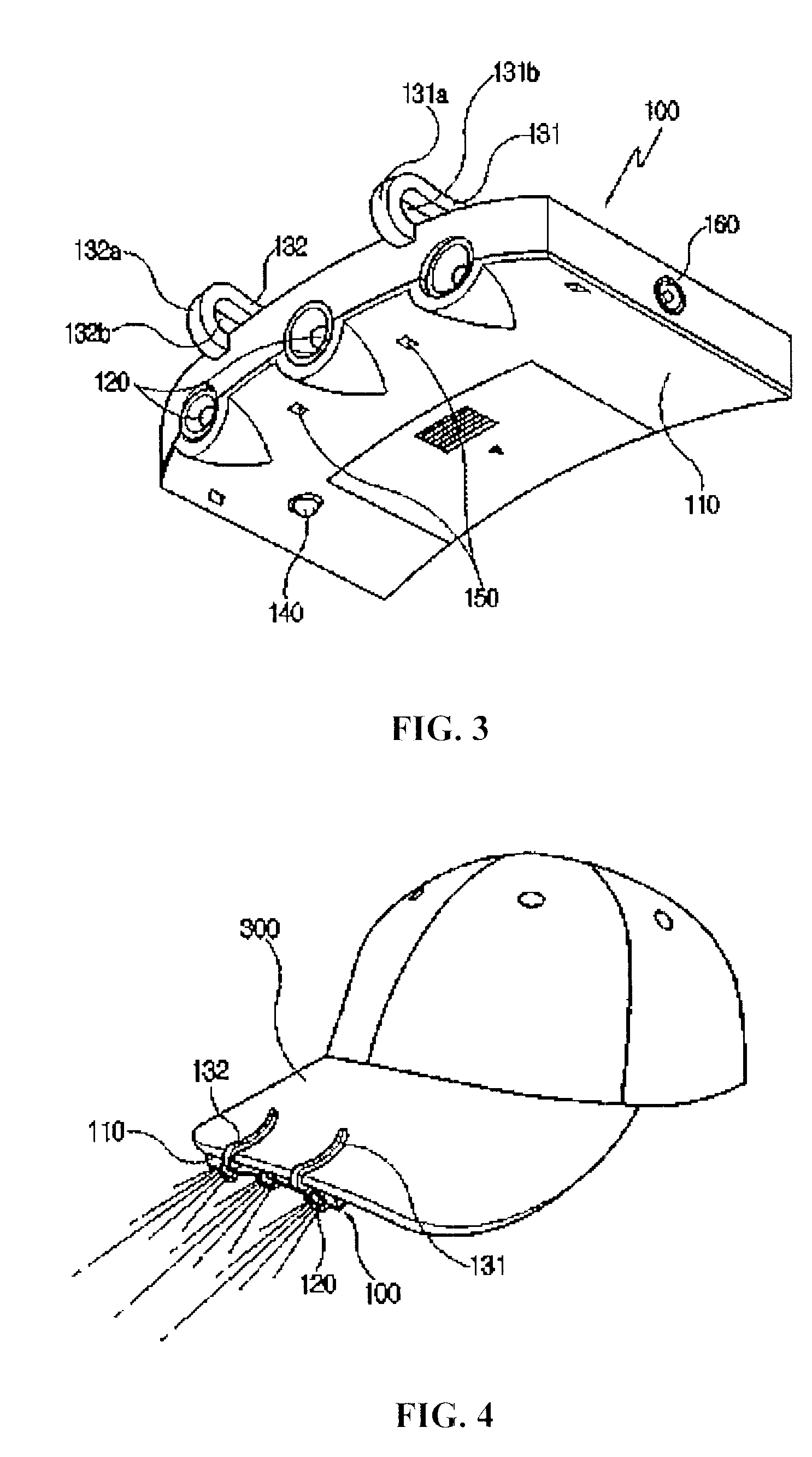
[0035] As shown in FIGS. 2, 3 and 4, the clip type light according to the present invention includes a body 110, in which a battery is accommodated. An upper portion of the body 110 closely adheres to a lower portion of a cap visor 300 having a smoothly curved surface. A plurality of electric lamps 120 are provided at the front portion of the body 110. First end portions of first and second clips 131 and 132 are fixed to the front portion of the body 110 and second end portions of the first and second clips 131 and 132 are elastically movable away from and towards the upper portion of the body 110.

[0036] The first and second clips 131 and 132 include first and second protrusions 131a and 132a, which have arc-shaped section and are integrally formed with the front portion of the body 110 while slightly protruding beyond the front portion of the body 110, and first and second clip fixing sections 135 and 136, which extend downward from the first and second protrusions 131a and 132a.

[...

second embodiment

[0054] Hereinafter, the clip type light according to the present invention will be described with reference to FIGS. 8 to 10. The same reference numerals will be used to refer to the same elements throughout the specification.

[0055]FIG. 8 is an exploded perspective view showing the clip type light according to the second embodiment of the present invention, FIG. 9 is a perspective view showing the clip type light shown in FIG. 8 coupled with a cap visor, and FIG. 10 is a side sectional view showing the clip type light coupled with the cap visor according to the second embodiment of the present invention.

[0056] The clip type light according to the second embodiment of the present invention is substantially identical to clip type light according to the first embodiment of the present invention, except that a pair of coupling holes 170 are formed at the front portion of the body 110 and a solar cell plate 200 is coupled with the body 110 through the coupling holes 170.

[0057] As shown...

third embodiment

[0062]FIG. 11 is a perspective view showing a clip type light according to the present invention, and FIG. 12 is a right-side view of FIG. 11.

[0063] The clip type light according to the third embodiment of the present invention is substantially identical to the clip type light according to the first embodiment of the present invention, except for the shape of the clip.

[0064] As shown in FIGS. 11 and 12, the clip type light according to the third embodiment of the present invention includes a clip section 400 coupled to the body 110 of the clip type light. The clip section 400 is provided with a head 410 having an arc-shaped section that protrudes upward in the front direction from the front portion of the body 110. First and second clip fixing sections 411 and 413 are provided at both sides of the head 410. The first and second clip fixing sections 411 and 413 extend along the upper surface of the body 110.

[0065] A locking hole 415 is defined by means of the head 410, and the rim ...


PUM


Abstract

A clip type light is detachably attached to a cap visor so as to ensure the user's field of vision. Two clips are integrally formed with both sides of a front section of a lamp body such that the two clips can be fixedly coupled with a front section of the cap visor regardless of the curved configuration of the visor. The clip type light can be easily attached to or detached from the cap visor without causing damage to the visor, and a switch for operating an electric lamp and an ultrasonic wave generator is provided at a lower portion of the lamp body in such a manner that the user can easily activate the electric lamp and the ultrasonic wave generator while wearing the cap equipped with the clip type light. A solar cell may also be provided to power the lamp and wave generator.

Description

CROSS-REFERENCE TO RELATED APPLICATIONS [0001] This application is a continuation-in-part of U.S. patent application Ser. No. 11 / 426,022 filed Jun. 23, 2006 (now U.S. Pat. No. 7,163,309), which is a continuation of U.S. patent application Ser. No. 10 / 758,107 filed Jan. 16, 2004 (now U.S. Pat. No. 7,118,241), both of which are incorporated by reference herein.FIELD OF THE INVENTION [0002] The present invention relates to a clip type light emitter, and in particular to a clip type light emitter capable of enhancing a visual field at night by detachably engaging a clip type light emitter to a hat or leisure cap generally used for sports, travel, etc. BACKGROUND OF THE INVENTION [0003] In general, in order to protect the face of a user from sunlight while ensuring the user's field of vision during leisure activity or sports activity, such as mountaineering, fishing, exercising, traveling, hiking, or jogging, the user wears a cap having a visor protruding from the front section of the ca...

Claims


Application Information

Patent Timeline
Patent Type & Authority Applications(United States)
IPC IPC(8): F21V21/084
CPCF21S9/037F21V21/084F21V21/088F21V21/0885F21V33/0052
Inventor SOHN, DAE UP
Owner SOHN
Learn More