
Video image encoder, video image decoder, and coded stream generation method

a video image encoder and encoder technology, applied in the direction of electronic editing digitised analogue information signals, instruments, television systems, etc., can solve the problems of data which should reference a parameter set, data processing becomes complicated, and inconvenience occurs

Inactive Publication Date: 2007-05-10
KK TOSHIBA
View PDF1 Cites 6 Cited by
  • Summary
  • Abstract
  • Description
  • Claims
  • Application Information

AI Technical Summary

Benefits of technology

The patent describes a method for generating a coded stream of video images that can be played back quickly using a fast-forward playback mode. The method separates the coded stream into information units and assigns a priority to each unit, so that the appropriate parameter set for playback is always provided. This allows for smooth playback and easy editing of the video images. The technical effect of this invention is to provide a reliable and efficient way to play back video images in a random access playback or skip playback mode.

Problems solved by technology

Thus, decode processing becomes complicated.
According to the above-mentioned rule, a problem would occur if decode processing of compression data is started at a midpoint in the stream or if decode processing of compression data is performed by random access after the stream is once recorded on a record medium.
This means that it may become impossible for data which should reference a parameter set to reference any desired parameter set.
To record the stream on an information record medium, such as a hard disk or a DVD, and play back the stream in a special mode, an inconvenience occurs.
If the parameter set placement is flexible as mentioned above, an inconvenience occurs in a skip playback mode.
That is, if PPS or SPS attached to a picture to be decoded with no skip is used to decode a picture to be played back while skipping, the picture may be unable to be played back.

Method used


Image

  • Video image encoder, video image decoder, and coded stream generation method
  • Video image encoder, video image decoder, and coded stream generation method
  • Video image encoder, video image decoder, and coded stream generation method

Examples


Embodiment Construction

[0037] Various embodiments according to the invention will be described hereinafter with reference to the accompanying drawings.

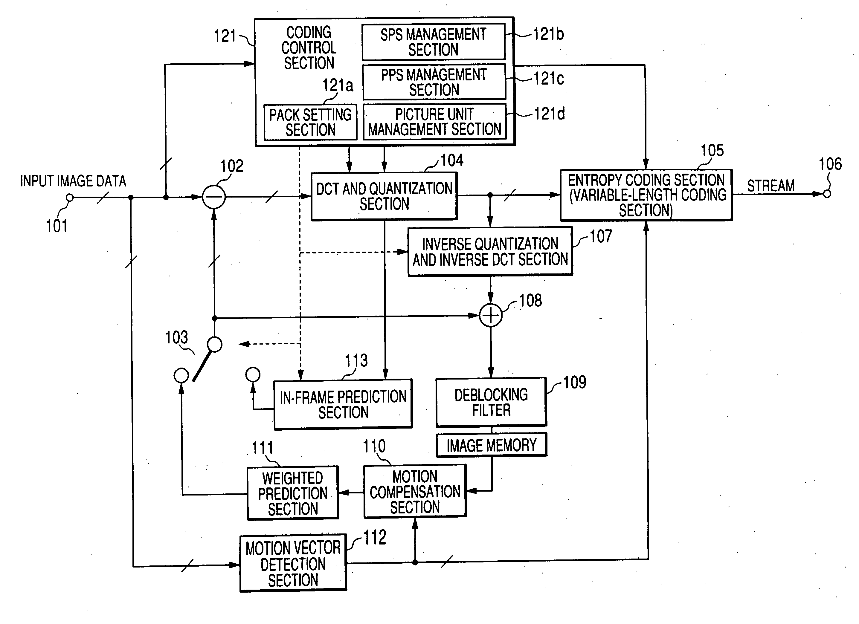
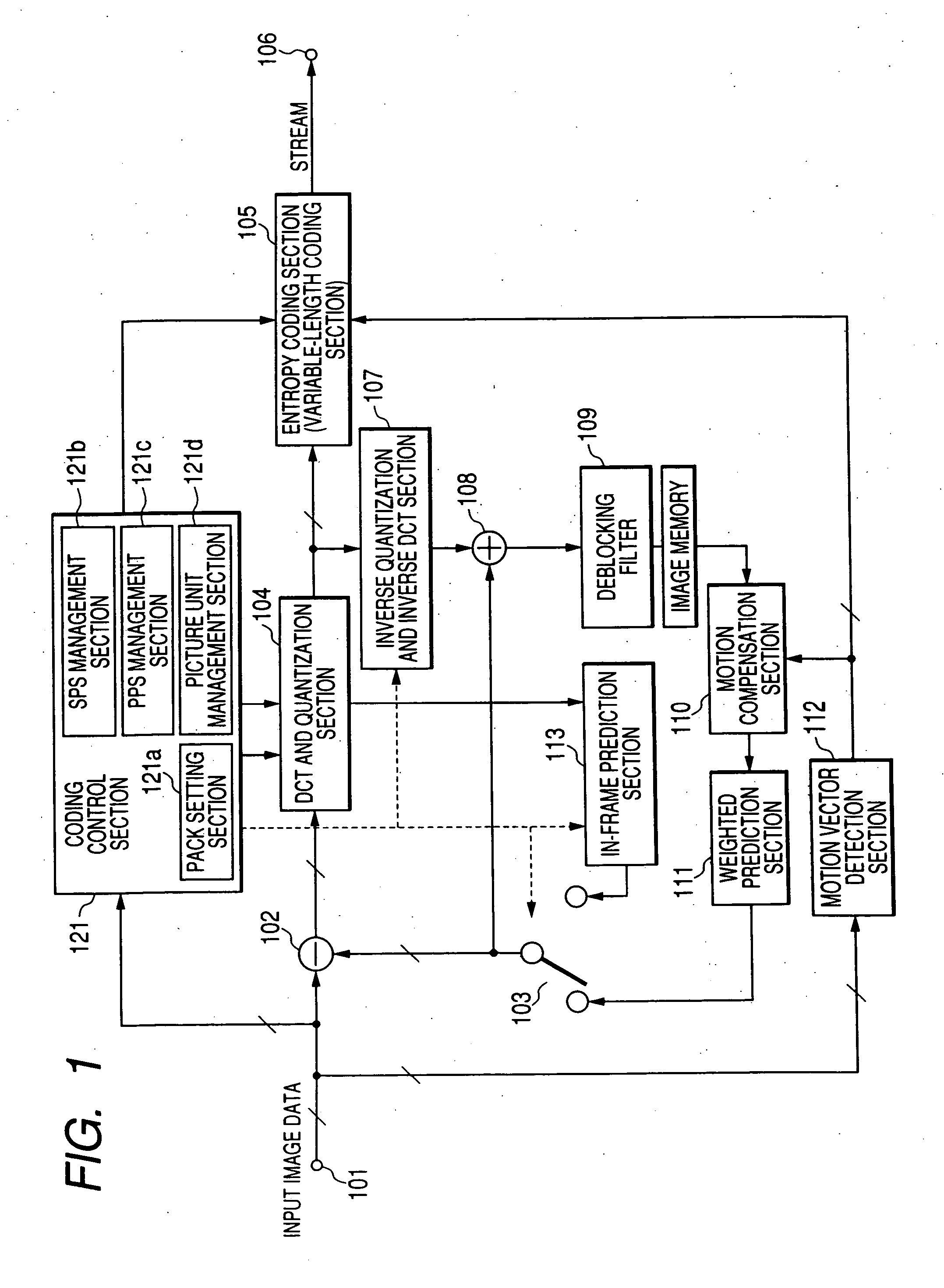
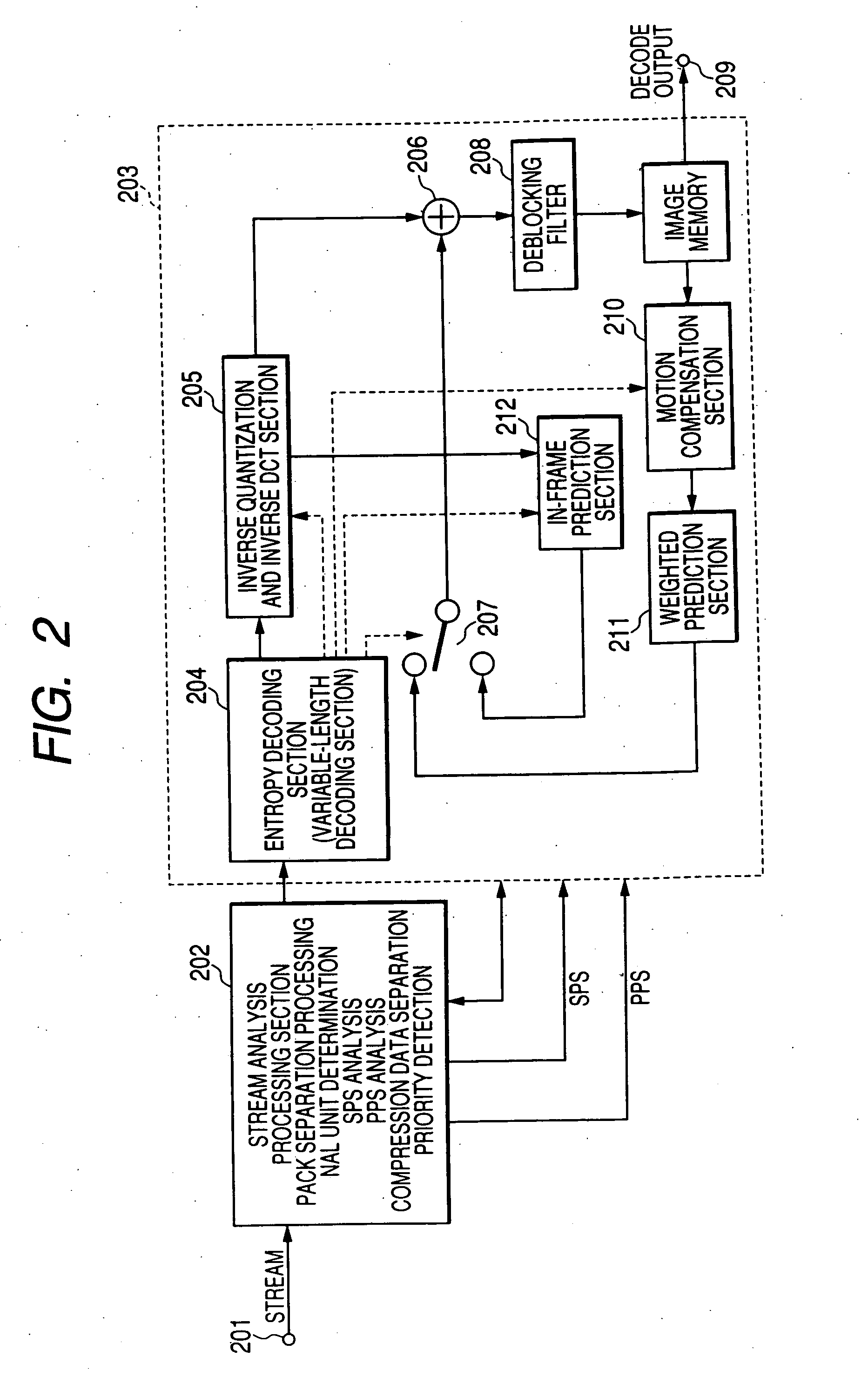
[0038] Referring now to the accompanying drawings, there is shown an embodiment. FIG. 1 schematically shows an encoder for coding image data based on H.264 / AVC standard. FIG. 2 schematically shows a decoder for decoding image compression data contained in a stream output from the encode in FIG. 1.

[0039] In FIG. 1, image data supplied to an input terminal 101 is supplied to a subtracter 102. When interframe processing is performed, the subtracter 102 subtracts image data from a switch 103 from the input image data. The output data of the subtracter 102 is subjected to discrete cosine transform processing and quantization processing in a DCT and quantization section 104. The output of the DCT and quantization section 104 is variable-length coded in an entropy coding section (which may be called a variable-length coding section) 105 and the result is output ...


PUM


Abstract

According to the embodiment, there is provided a coded stream generation method for generating a coded stream including a plurality of first units and a plurality of second units that are arranged in a time series. The method includes; separating the coded stream into a plurality of information units and defining a third unit containing the first units and the second units for each of the information units; assigning a first priority to the initial first unit and to the first units to be decoded as standard data in performing a fast-forward playback mode; assigning a second priority that is lower than the first priority to the first units to be decoded as reference data in performing the fast-forward playback mode; and assigning a third priority that is lower than the second priority is to the first units to be undecoded in performing the fast-forward playback mode.

Description

CROSS-REFERENCE TO RELATED APPLICATIONS [0001] This application is based upon and claims the benefit of priority from Japanese Patent Application No. 2005-024578, filed on Jan. 31, 2005, the entire contents of which are incorporated herein by reference.BACKGROUND [0002] 1. Field [0003] One embodiment of the invention relates to a video image encoder, a video image decoder, and a coded stream generation method and in particular to an art of devising the management method and placement of a unit containing a parameter set required for decoding image compression data for convenience of handling data when performing decoding processing of image compression data and also covers the structure of a stream. The embodiment devises the data structure convenient for recording data on a record medium, for example, a video disk and also effective for playing back or editing the data from the video disk. [0004] 2. Description of the Related Art [0005] In recent years, the coding and decoding tech...

Claims


Application Information

Patent Timeline
Patent Type & Authority Applications(United States)
IPC IPC(8): H04N11/04H04N5/93H04N19/00H04N19/169H04N19/46H04N19/503H04N19/51H04N19/61H04N19/625H04N19/70H04N19/80H04N19/86H04N19/91
CPCG11B27/005H04N19/188G11B27/105G11B2220/2562H04N5/783H04N5/85H04N9/8042H04N9/8205H04N19/70H04N19/172H04N19/46H04N19/196H04N19/61H04N19/37H04N19/132H04N19/174G11B27/034
Inventor KIKUCHI, YOSHIHIRO
Owner KK TOSHIBA
Learn More