
Transmissive phase plate, polarized beam splitter, and projection display

a technology of polarized beam splitter and transmission phase, which is applied in the direction of optical elements, record information storage, instruments, etc., can solve the problems of degradation of contrast ratio of picture images projected on the screen, failure to satisfactorily split light according to intended optical characteristics, and failure to achieve the effect of preventing degradation of contrast ratio

Inactive Publication Date: 2007-05-10
FUJI PHOTO OPTICAL CO LTD
View PDF13 Cites 32 Cited by
  • Summary
  • Abstract
  • Description
  • Claims
  • Application Information

AI Technical Summary

Benefits of technology

[0014] In view of the foregoing situations, it is an object of the present invention to prevent degradations in contrast ratio of projected picture images which usually take place when a divergent or convergent light flux is fed to a polarized beam splitter, using a polarization-correcting optical multi-layer coating (hereinafter referred to simply as “correcting optical multi-layer coating“ for brevity) which is formed by alternately laminating a high refractivity layer and a low refractivity layer, without resorting to a special deposition film or crystal axis.

Problems solved by technology

In this connection, in case incident light on the polarized beam splitter is a divergent light flux, there arises a problem that contrast ratio is degraded by transmission of part of s-polarized light which should be reflected off by the polarized beam splitter.
Likewise, when the direction of polarization is inclined relative to the direction of polarization of s-polarized light, 100% reflection does not take place because part of light is transmitted through, resulting in a failure to split light satisfactorily according to intended optical characteristics.
Therefore, part of light rays which should be reflected by a polarized beam splitter is transmitted through and projected on a screen, giving rise to a problem of degradations in contrast ratio of picture images projected on a screen.
However, an optical film has a problem that it is unsatisfactory in resistance to weather, and a quartz plate has an inherent problem that it is limited in size.

Method used


Image

  • Transmissive phase plate, polarized beam splitter, and projection display
  • Transmissive phase plate, polarized beam splitter, and projection display
  • Transmissive phase plate, polarized beam splitter, and projection display

Examples


Embodiment Construction

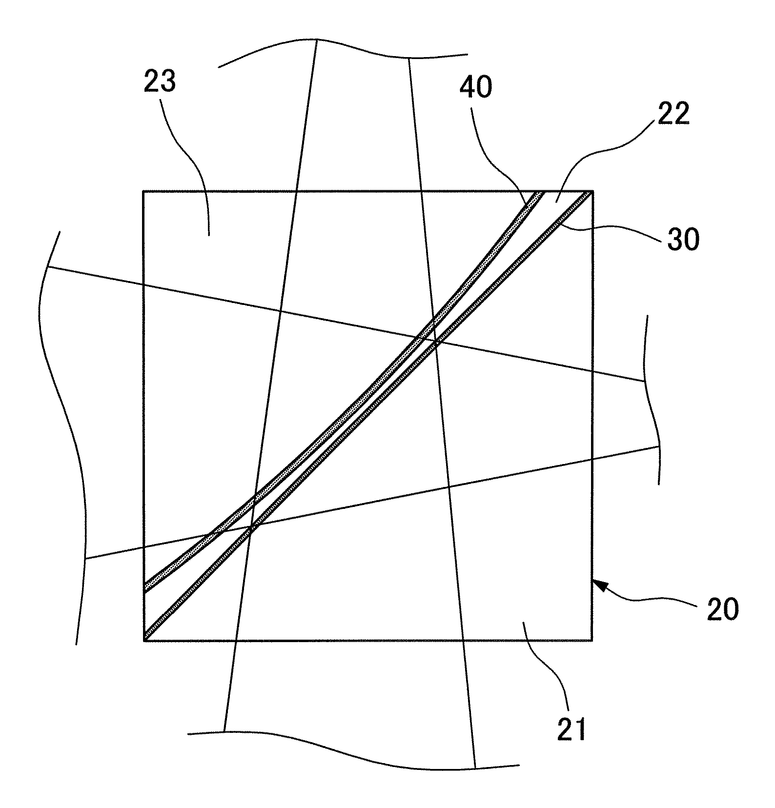
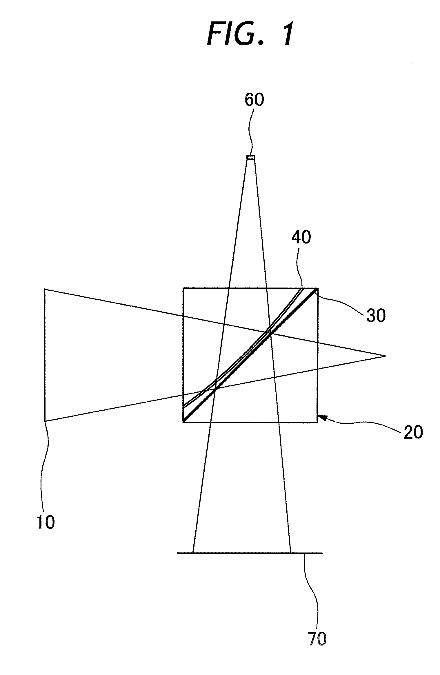
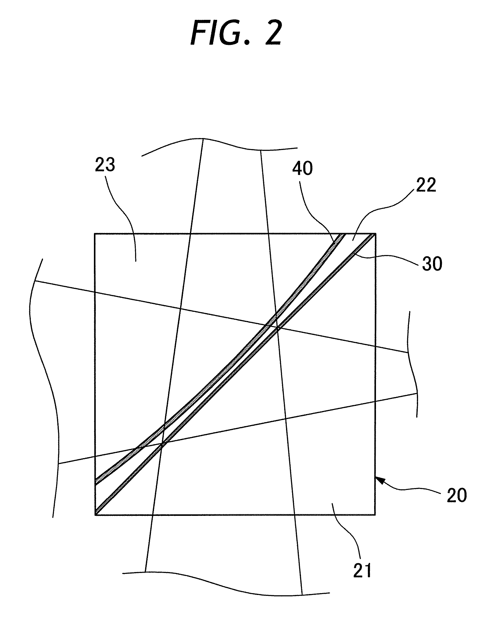
[0026] Hereafter, the present invention is described more particularly by way of its preferred embodiments with reference to the accompanying drawings. Shown in FIG. 1 is an LCOS reflection type liquid crystal projector as an example of a projection display to which the present invention is applicable. Here, the present invention is described by way of an LCOS projection type liquid crystal projector, but it should be understood that the present invention can be applied to other projection type displays such as transmission type liquid crystal projector or the like. In FIG. 1, the projection type display according to the invention includes a light source 10, polarized beam splitter 20, reflective light valve 50 and screen 70. Arbitrary light such as random polarization light or linear polarization light like p- or s-polarized light is emitted from the light source 10. Light from the light source 10 is in the form of a convergent light flux which is converged toward the reflective li...


PUM


Abstract

A transmissive phase plate with a function of correcting direction of polarization of light rays in an incident divergent or convergent light flux in addition to functions as a wave plate. Conditions of polarization of incident light rays are corrected by a polarization-correcting optical multi-layer coating which is formed by alternately depositing a high refractivity layer and a low refractivity layer on curved substrative surface of a predetermined radius of curvature. The transmissive phase plate can be applied to correct conditions of polarization of incident light rays of a polarized beam splitter for the purpose of improving contrast ratio of a projection display.

Description

BACKGROUND OF THE INVENTION [0001] 1. Field of the Art [0002] This invention relates to a transmissive phase plate with a function of correcting direction of polarization, a polarized beam splitter embodying the transmissive phase plate for correction of polarization of incident light, and a projection type display incorporating the polarized beam splitter with a polarization-correcting transmissive phase plate. [0003] 2. Prior Art [0004] A diversity of projection type display devices like liquid crystal projectors have been introduced and in use, but recently reflective liquid crystal projectors of LCOS (Liquid Crystal on Silicon) technology came into use. Different from transmissive liquid crystal projectors, LCOS reflective liquid crystal projectors have liquid crystal elements drive circuits located on the rear side of reflection mirrors. Therefore, in the case of a LCOS liquid crystal projector, it is possible to realize production of high quality picture images by narrowing ga...

Claims


Application Information

Patent Timeline
IPC IPC(8): G11B7/135
CPCG02B5/3041G02B5/3083G02B27/283G02B27/286G03B21/2073
Inventor KATO, SHIGERUKOMATSU, TAKUYAKAWAMURA, YOSHIJI
Owner FUJI PHOTO OPTICAL CO LTD
Learn More