
System and method for constructing a backlighted display using dynamically optimized light source

a dynamic optimization and light source technology, applied in static indicating devices, lighting and heating apparatuses, instruments, etc., can solve the problem of inefficient lumen/watt output of green leds

Inactive Publication Date: 2007-05-10
AVAGO TECH ECBU IP (SINGAPORE) PTE LTD
View PDF11 Cites 30 Cited by
  • Summary
  • Abstract
  • Description
  • Claims
  • Application Information

AI Technical Summary

Benefits of technology

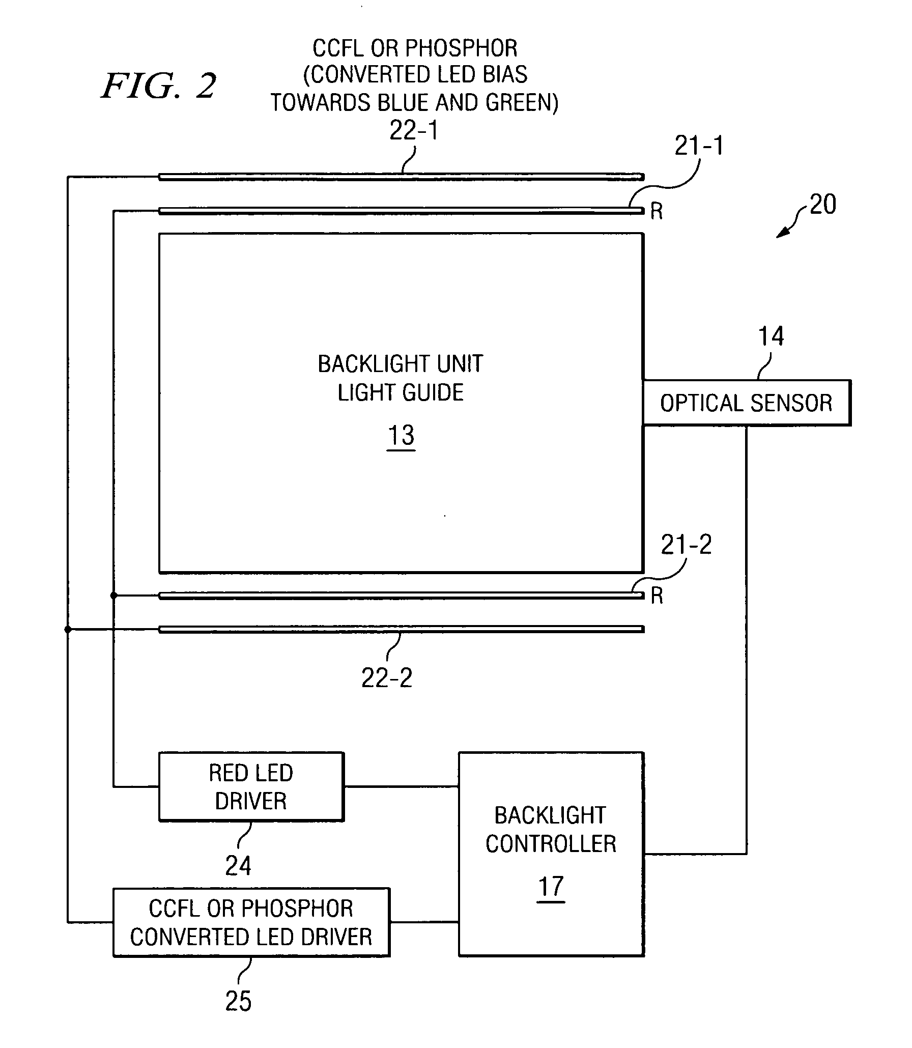
[0004] A combination of light source types is used to form a dynamically adjusted backlighted display with the particular combination dependant upon the desired light output at a given point in time. In one embodiment, RGB diodes are used for low brightness situations and as the brightness requirement increases white light sources are added. In another embodiment, different light source types are used to produce the different color components and optical feedback is used to control the power levels of the various diode types.

Problems solved by technology

However, because their light output (primarily the green LED) is not as efficient in lumens / watt as CCFLs or white diodes more RGB diodes are required.

Method used


Image

  • System and method for constructing a backlighted display using dynamically optimized light source
  • System and method for constructing a backlighted display using dynamically optimized light source
  • System and method for constructing a backlighted display using dynamically optimized light source

Examples


Embodiment Construction

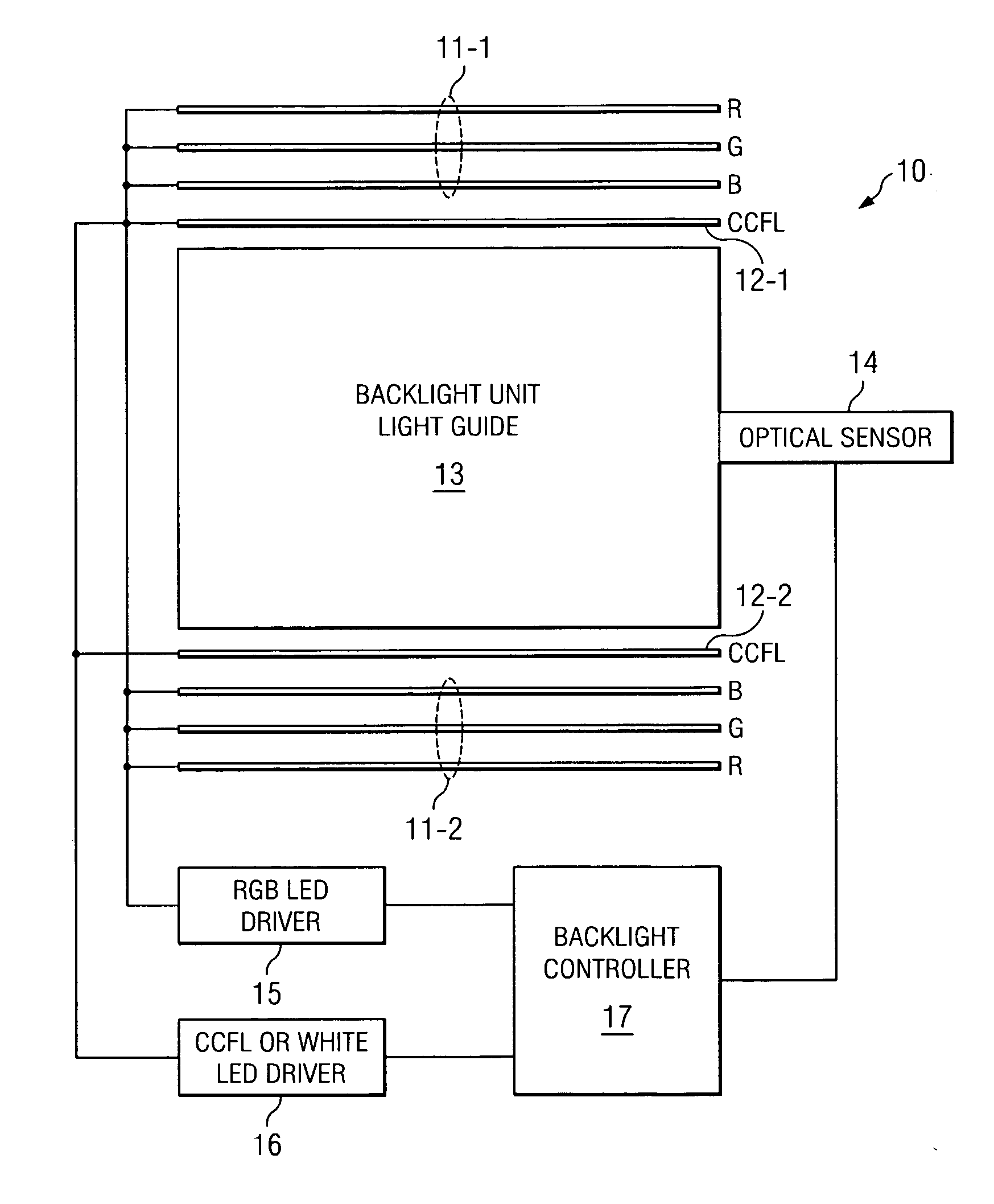
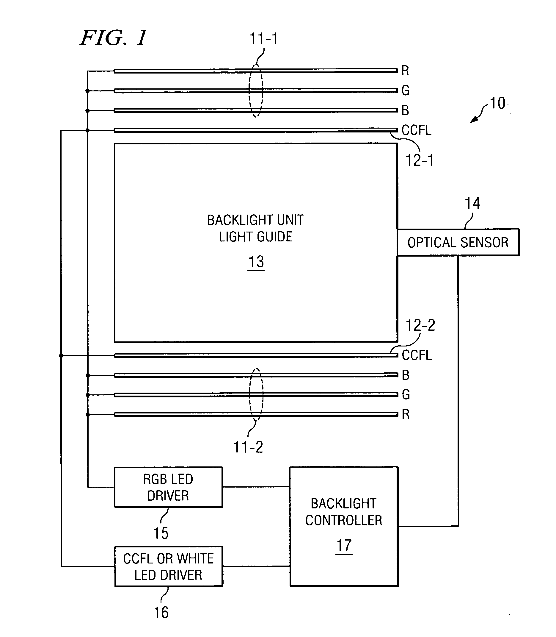
[0009]FIG. 1 shows one embodiment of backlighted display 10 having light guide 13 and having two independently controllable light sources 111 and 12. In this embodiment, light source 11 (11-1, 11-2) is one or more RGB LED arrays and light source 12 (12-1, 12-2) is a CCFL or white LED source. Note that the white light source can be a single diode array or could be a plurality of red, green, blue (or other colors) CCFLs or phosphor covered LEDs biased to achieve white light.

[0010] Optical sensor 14 can determine both the color of the light and the intensity of the light. In this embodiment the intensity is important such that backlight controller 17 will use readings from sensor 14 to increase RGB LED driver 15 until a point is reached where further power to RGB LED driver 15 will not increase the lumen output. As shown in FIG. 3A, line 30 represents the increase in lumen output of RGB LED until point 301. When point 301 is reached, the lumen output goes essentially flat.

[0011] At t...


PUM


Abstract

A combination of light source types is used to form a dynamically adjusted backlighted display with the particular combination dependant upon the desired light output at a given point in time. In one embodiment, RGB diodes are used for low brightness situations and as the brightness requirement increases white light sources are added. In another embodiment, different light source types are used to produce the different color components and optical feedback is used to control the power levels of the various diode types.

Description

TECHNICAL FIELD [0001] This invention relates to backlighted displays and more particularly to light sources that are dynamically adjustable to achieve a desired output brightness. BACKGROUND OF THE INVENTION [0002] It has become common to use backlighted displays for a variety of purposes. One such usage is in cellular phones, PDAs, cameras and other handheld devices. In many of these applications it is desired to have white back light and thus such displays typically use white (phosphor converted) light emitting diodes (LEDs) or cold crystal fluorescent lamps (CCFL) in conjunction with a liquid crystal display (LCD) to form the backlighted device. [0003] Because a wider color gamut is often required than is available with CCFL or white LEDs, backlighted devices are beginning to use red, green and blue (RGB) LEDs. The light output of these red, green and blue LEDs are mixed to produce the required color. However, because their light output (primarily the green LED) is not as effici...

Claims


Application Information

Patent Timeline
Patent Type & Authority Applications(United States)
IPC IPC(8): F21V7/04H01L33/00
CPCG02B6/0068G02B6/0073G09G3/3413G09G2320/0633G09G2320/0666G09G2360/145
Inventor KEH, KEAN LOOLIM, KEVIN LEN LILEE, JOON CHOKYAP, EIT THIANOON, CHIN HIN
Owner AVAGO TECH ECBU IP (SINGAPORE) PTE LTD
Learn More