Hydraulic full power brake system for trailers

Inactive Publication Date: 2007-05-10
MERITOR WABCO VEHICLE CONTROL SYST
View PDF18 Cites 39 Cited by
  • Summary
  • Abstract
  • Description
  • Claims
  • Application Information

AI Technical Summary

Benefits of technology

[0007] The power unit includes an electric motor that is controlled by the ECU. The electric motor drives a pump to maintain a desired pressure level in an accumulator. The pump supplies hydraulic fluid to the accumulator from a trailer supply reservoir. The pressure in the accumulator is monitored and controlled by the ECU by using a pressure transducer. A pressure limiting valve prevents over-pressure conditions.

Problems solved by technology

However, neither method offers control for emergency stopping situations.
In an emergency stopping situation a trailer has increased potential for jack-knifing or roll-over events.
Further, neither method offers anti-lock control to prevent wheel lock-up under poor road conditions.

Method used


Image

  • Hydraulic full power brake system for trailers
  • Hydraulic full power brake system for trailers
  • Hydraulic full power brake system for trailers

Examples


Embodiment Construction

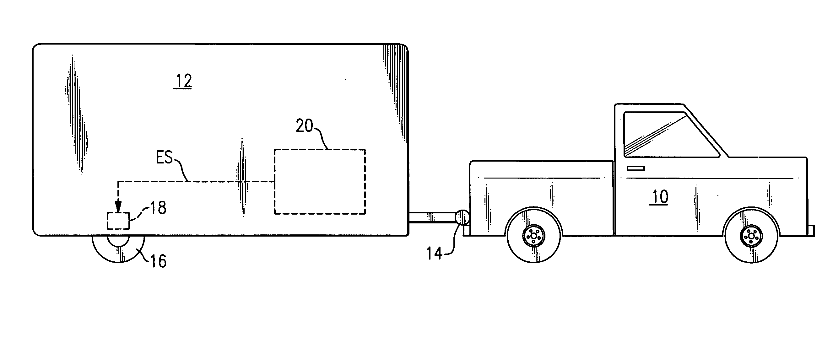
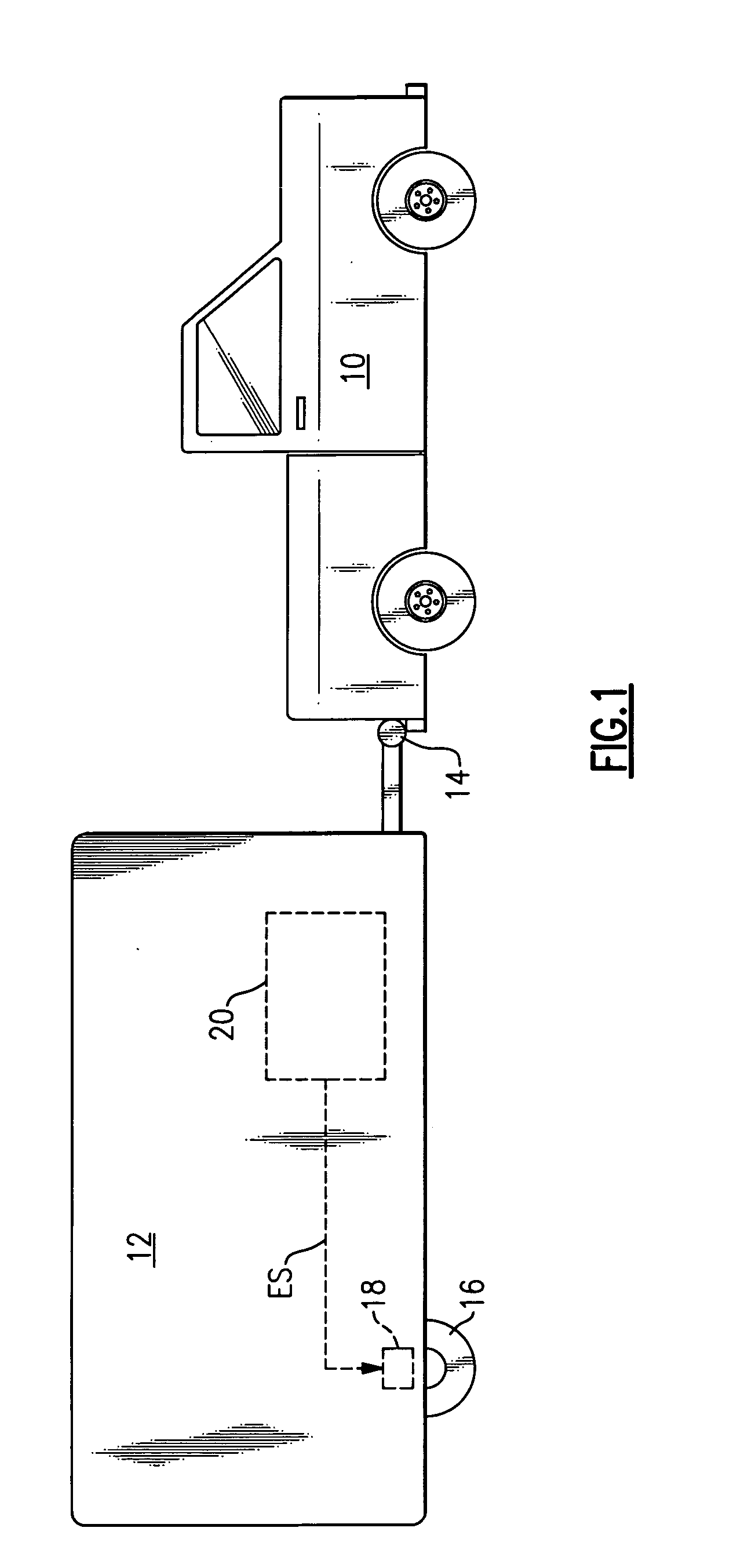
[0015]FIG. 1 shows a light to medium duty vehicle 10 that is connected to a trailer 12 with a hitch 14. Optionally, the trailer 12 could be towed through a fifth wheel connection (not shown). The trailer 12 includes at least one axle having a set of wheels 16 (only one wheel is shown in FIG. 1). The wheel 16 includes a wheel brake member, which is schematically indicated at 18. The wheel brake member 18 is preferably a disc brake with a caliper that is hydraulically actuated, however, other types of hydraulically actuated wheel brakes could also be used.

[0016] A trailer brake system 20 generates an electric control signal ES that is used to hydraulically actuate the wheel brake member 18 in response to a braking request. Thus, the trailer brake system 20 provides an electric over hydraulic system for the trailer 12.

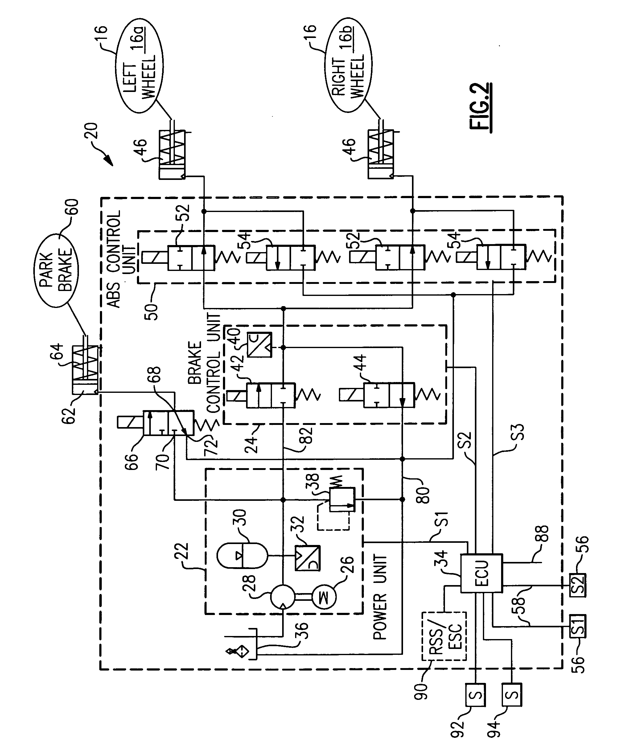
[0017] The trailer brake system 20 is shown in greater detail in FIG. 2. The trailer brake system includes a power unit 22 and a brake control unit 24. The power unit 2...


PUM


Abstract

A trailer brake system includes a full power hydraulic brake system that is electrically controlled by a system control unit. The trailer brake system includes a power unit that maintains a pressurized supply of hydraulic fluid and a brake control unit that is fluidly connected between the power unit and trailer wheel brake components. The power unit includes an electric motor driven pump and accumulator that is in fluid communication with a trailer supply reservoir. The brake control unit includes an inlet valve that is fluidly connected to the accumulator and an outlet valve that is fluidly connected to the trailer supply reservoir. The system control unit generates control signals to the power unit and brake control unit to respectively maintain a desired pressure level in the accumulator, and to apply the trailer wheel brake components through the brake control unit.

Description

TECHNICAL FIELD [0001] The subject invention relates to a hydraulic brake system for a trailer towed by a passenger car or light to medium duty truck where the hydraulic brake system is electronically controlled. BACKGROUND OF THE INVENTION [0002] Light to medium duty vehicles, such as passenger cars, pick-up trucks, sport utility vehicles, etc., are often configured to pull trailers. These trailers are typically utility or work trailers but can include horse trailers and recreational trailers, such as campers, for example. These types of trailers typically include medium duty trailer brakes that are controlled by one of two different methods. [0003] One method uses electronic control for actuating magnetic brakes at each trailer wheel. An electrical control signal is used to generate a magnetic brake actuation force. Another method uses hydraulic surge brake control to actuate hydraulic brakes. This is often referred to as a hydraulic over hydraulic system. During a braking event, ...

Claims


Application Information

Patent Timeline
IPC IPC(8): B60T13/74
CPCB60T7/20B60T13/745
Inventor KELLY, RALPH D.WOHLTMANN, DIRK
Owner MERITOR WABCO VEHICLE CONTROL SYST
Why Eureka
Try Eureka